88192278-01-19 Installation Master.pdf - 第168页
PRINTER PREPARATION PRINTER ASSEMBLY 4.66 Installation Manual Chapter Issue 15, May 20 2. Move the angle brackets aw ay from the support plate. 3. Remove the rear cover of the printer (front cover on type 4 printers). 4.…
PRINTER PREPARATION
PRINTER ASSEMBLY
Chapter Issue 15, May 20 Installation Manual 4.65
External Solvent Tank
MANDATORY
TOXIC CHEMICALS MAY BE PRESENT. SAFETY GLOVES MUST BE WORN.
MANDATORY
TOXIC CHEMICALS MAY BE PRESENT. EYE PROTECTION MUST BE WORN.
NOTE
Changing solvent types may cause unexpected chemical reactions and
degradation within the solvent feed tube. ASM recommend that if the solvent is
changed to a different type, the solvent feed tube, from the solvent tank to the
cleaner pump, is replaced.
For printer types 1 - 4 the external solvent tank may be fitted to the rear or the
side of the printer. The support plate on the external solvent tank is configured
differently from side or rear fitting due to baffle plates covering the cooling fans
at the rear of the printer.
The external solvent tank used on type 5 printers is free standing.
To fit the external solvent tank to printer types 1 - 4, carry out the following:
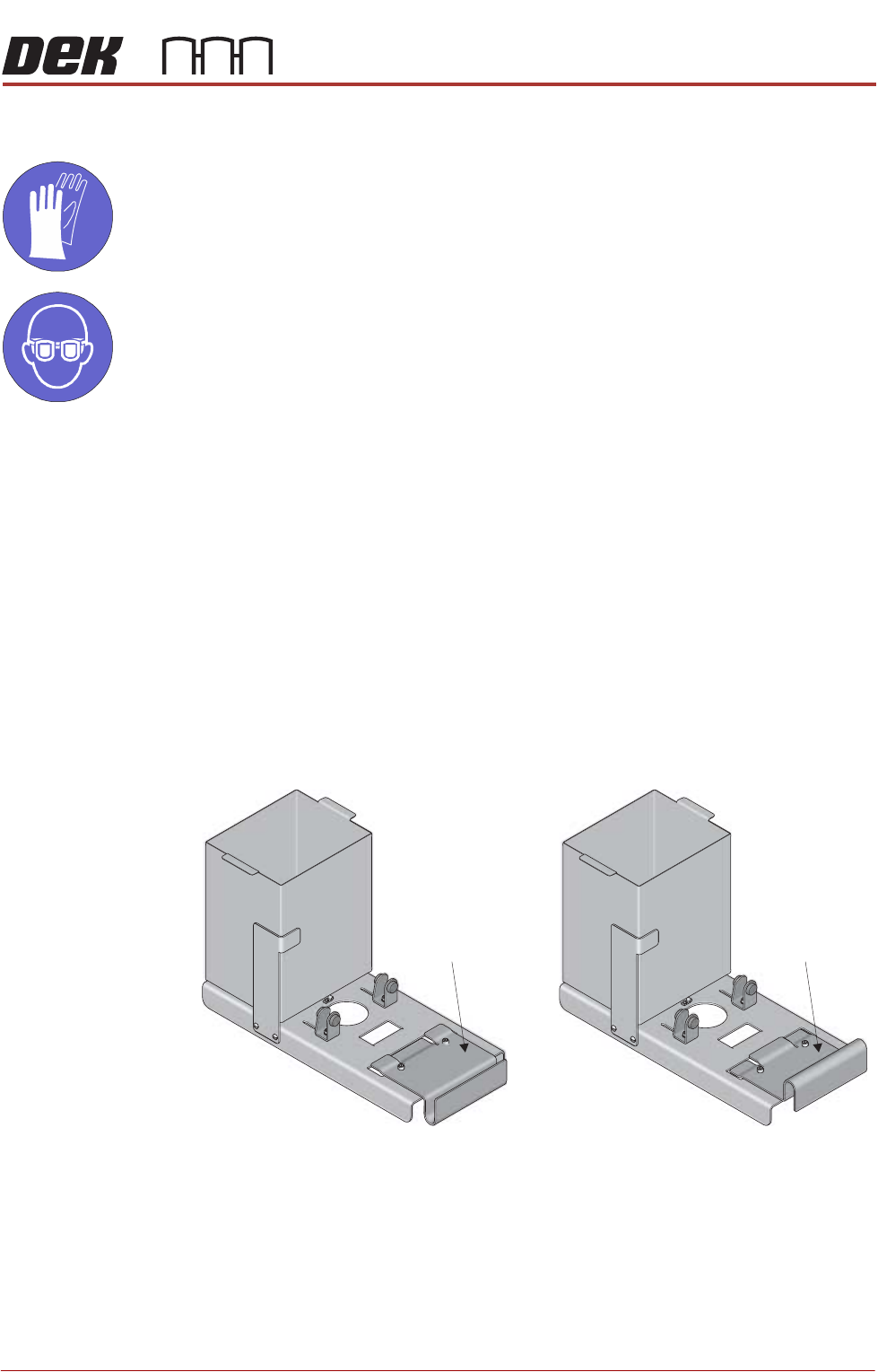
1. Configure the support plate of the external solvent tank for rear or side fitting
to the printer.
Rear Fitting Side Fitting
Support Plate Support Plate
PRINTER PREPARATION
PRINTER ASSEMBLY
4.66 Installation Manual Chapter Issue 15, May 20
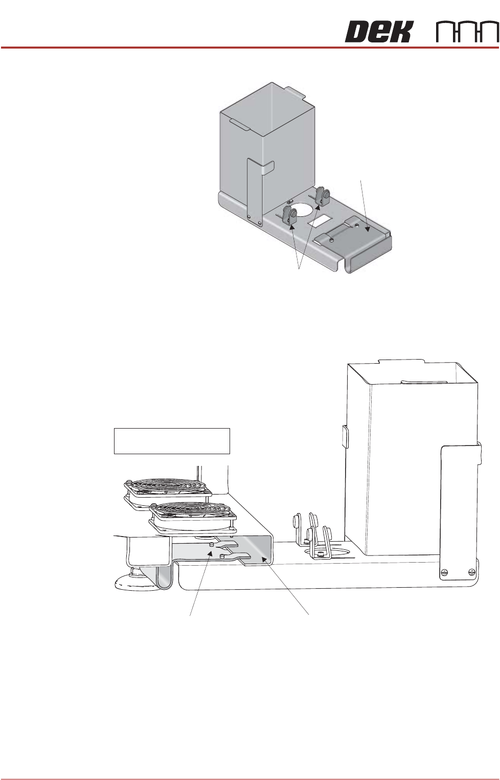
2. Move the angle brackets away from the support plate.
3. Remove the rear cover of the printer (front cover on type 4 printers).
4. Place the external solvent tank on the floor beneath its intended location.
5. Supporting its weight, lift the external solvent tank and locate the support
plate on the printer base frame, as shown in the graphic below:
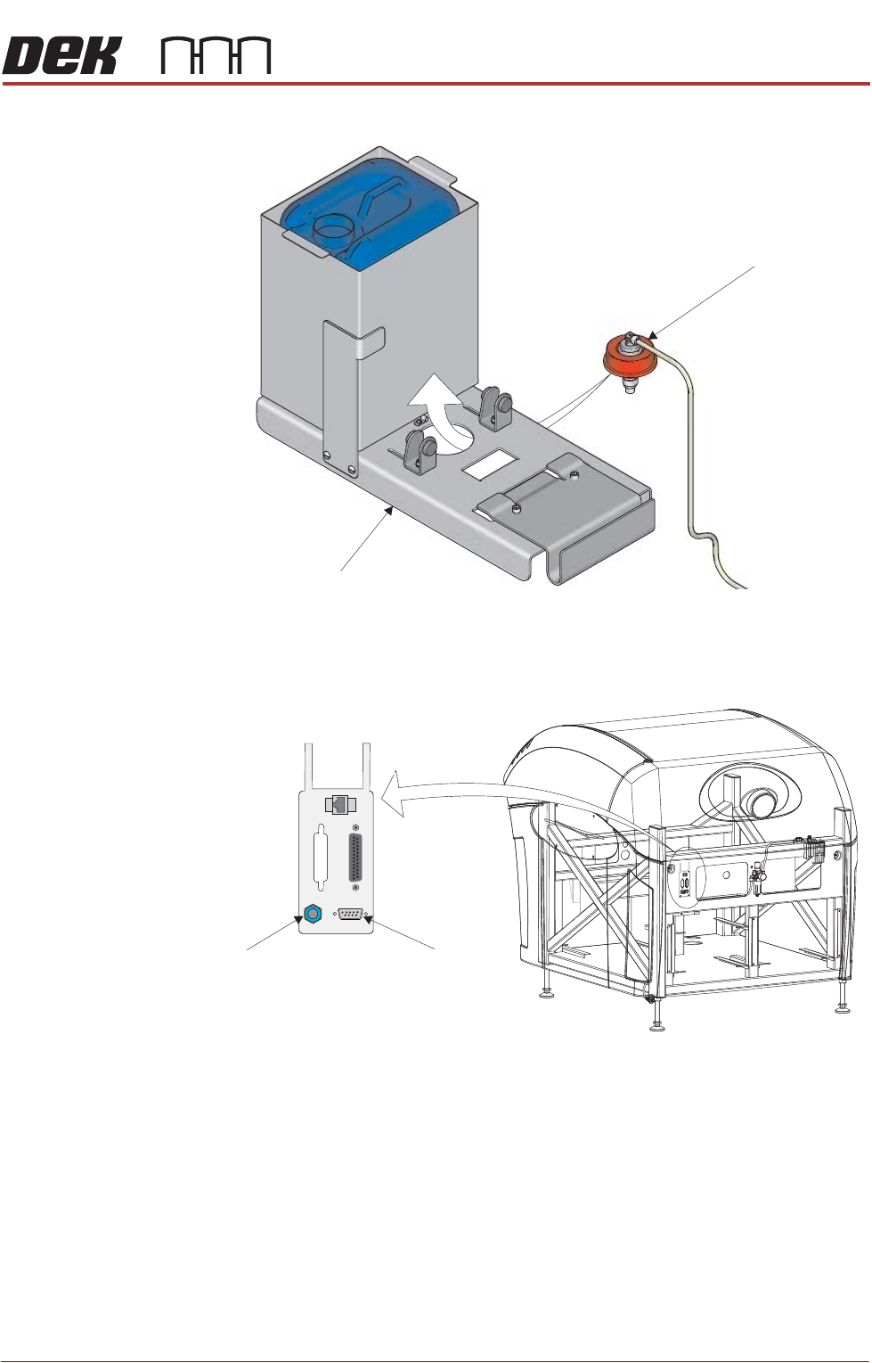
6. Place a full solvent container into the external solvent tank.
7. Remove the cap from the solvent container.
8. Locate the combined solvent container cap and 4mm tubing, inside the
printer.
9. Pass the cap through the hole in the external solvent tank base plate, from
Support Plate
Angle Brackets
Support Plate Machine Base Frame (Cross Section)
NOTE
Baffles removed for clarity
PRINTER PREPARATION
PRINTER ASSEMBLY
Chapter Issue 15, May 20 Installation Manual 4.67
underneath.
10. Fit the combined cap and 4mm tubing to the solvent container.
11. Connect the cable from the external solvent tank to 9SK69 on the external
services panel.
12. Fit the rear cover (front cover on type 4 printers).
Solvent Container Cap
Base Plate
View on Rear of Machine
POWER ON
PART No. 160740
M/C AVAILABLE
BOARD AVAILABLE
BOARD PASS
D
O
W
N
L
IN
E
BOARD AVAILABLE
BOARD PASS
M/C AVAILABLE
U
P
L
IN
E
FMI POD
Solvent Fluid
Connector
Solvent Sensor
9SK69