88192278-01-19 Installation Master.pdf - 第185页
POWER UP SEQUENCE MACHINE POWER UP SEQU ENCE Chapter Issue 10, Nov 19 Installation Manual 5.9 T o setup the USC carry out the following: 1. Ensure that the external solvent tank is fitted with an empty 5 litre cont ainer…
POWER UP SEQUENCE
MACHINE POWER UP SEQUENCE
5.8 Installation Manual Chapter Issue 10, Nov 19
E Stop Loop
Operation
Carry out the following procedure for E Stop loop operation check:
1. Press the E Stop button. The Restore System Power window is displayed.
2. Reset the E Stop by turning the E Stop button clockwise until it unlatches.
3. Press the System button when prompted.
4. Open the printhead cover. The Machine Operation Suspended - Cover
Open window is displayed.
5. Close the printhead cover.
6. Press the System button when prompted.
Cover Open
Operation
1. After initialisation, open the printhead cover. The open cover page is dis-
played.
2. Close the printhead cover.
3. Press the System button to check that system power is restored.
Screen Cleaner Function Check
CAUTION
RECOMMENDED SOLVENTS. ANY SOLVENTS USED MUST COMPLY WITH
LOCAL ENVIRONMENTAL GUIDELINES. ASM RECOMMEND USING SOLVENTS
THAT ARE ENVIRONMENTALLY FRIENDLY, IE CFC FREE AND WATER BASED.
SOLVENTS USED MUST HAVE FAST EVAPORATION RATES AND FLASHPOINT
SPECIFICATIONS GREATER THAN 39ºC.
WARNING
SOLVENT SPRAY. THE UNDER STENCIL CLEANER SPRAYS A FINE JET OF
SOLVENT SOLUTION ON TO THE CLEANER. APPROVED PROTECTIVE
CLOTHING SHOULD BE WORN.
CAUTION
PRINT MEDIUM AND SOLVENTS. WHEN USING OR HANDLING ANY PRINT
MEDIUM OR SOLVENT FORMULATION THE MANUFACTURERS’ SAFETY DATA
SHEETS MUST BE STRICTLY ADHERED TO.
MANDATORY
TOXIC CHEMICALS MAY BE PRESENT. SAFETY GLOVES MUST BE WORN.
MANDATORY
TOXIC CHEMICALS MAY BE PRESENT. EYE PROTECTION MUST BE WORN.
NOTE
If the Under Stencil Cleaner has not been used for lengthy periods, refer to
Technical Bulletin TB 329 to complete the cleaning regime for the spray bar.

POWER UP SEQUENCE
MACHINE POWER UP SEQUENCE
Chapter Issue 10, Nov 19 Installation Manual 5.9
To setup the USC carry out the following:
1. Ensure that the external solvent tank is fitted with an empty 5 litre container.
2. Select Maintenance.
3. Select Calibrations.
4. Select Classic Calibrations.
5. Select Solvent.
6. Select Set Solv Empty.
7. Confirm by selecting Yes.
8. Replace the empty 5 litre container with a 5 litre container full of the solvent
to be used.
9. Select Set Solv Full.
10. Confirm by selecting Yes.
11. Select Exit.
12. Select Exit.
13. Select Back.
14. Select Open Cover Commands.
15. Open the printhead cover.
16. Select Prime Solvent.
17. When prompted, press the two button control switches simultaneously until
the paper is wet (this may take several attempts before solvent is sprayed
onto the paper).
18. Select Back.
19. Select Prime Paper.
20. When prompted, press the two button control switches simultaneously to
feed a clean area of dry paper over the solvent dispense pipe ensuring that
the paper feeds correctly.
21. Select Back.
22. Close the printhead cover and press the System button.
23. Select Back.
Paste Dispenser
Function Check
To check that the paste dispenser level sensor works with the customers’ paste,
use the following procedure:
1. Select Maintenance.
2. Select Diagnostics.
3. Using the Next or Previous buttons to highlight Paste Dispenser System.
4. Select Select Module.
5. Note that the Paste Cartridge Empty is displaying ON.
6. Open printhead cover.
7. Fit a full paste cartridge containing the paste to be used by the customer.
8. Move the paste dispenser by hand so that the paste level sensor is aligned
with the paste in the cartridge.
POWER UP SEQUENCE
MACHINE POWER UP SEQUENCE
5.10 Installation Manual Chapter Issue 10, Nov 19
9. Ensure that the Paste Cartridge Empty is displaying OFF.
10. Paste consistency varies throughout the cartridge, ensure the sensor can
detect paste throughout the length of the cartridge without the Paste Car-
tridge Empty switching to ON.
NOTE
If adjustment of the paste level sensor is required, refer to the Technical
Reference manual - Paste Dispenser System - Adjustments and Settings
section.
11. Close printhead cover.
12. Press the System button.
13. Select Exit.
14. Select Exit.
15. Select Back.
ProFlow Contact
Position Setup
For machines using ProFlow only, set up the contact height position as follows:
1. Select Open Cover Commands.
2. Select Carriage To Front.
3. Open the printhead cover.
4. Load the calibration screen into the chase.
5. Fit an empty transfer head to the ProFlow pressure mechanism and remove
the ProFlow cover.
6. Position a 0.1mm shim on the stencil under the transfer head.
7. Close the printhead cover.
8. Press the System button.
9. Select Back.
10. Select Load Screen.
11. Select Maintenance.
12. Select Calibrations.
13. Select Classic Calibrations.
14. Select ProFlow.
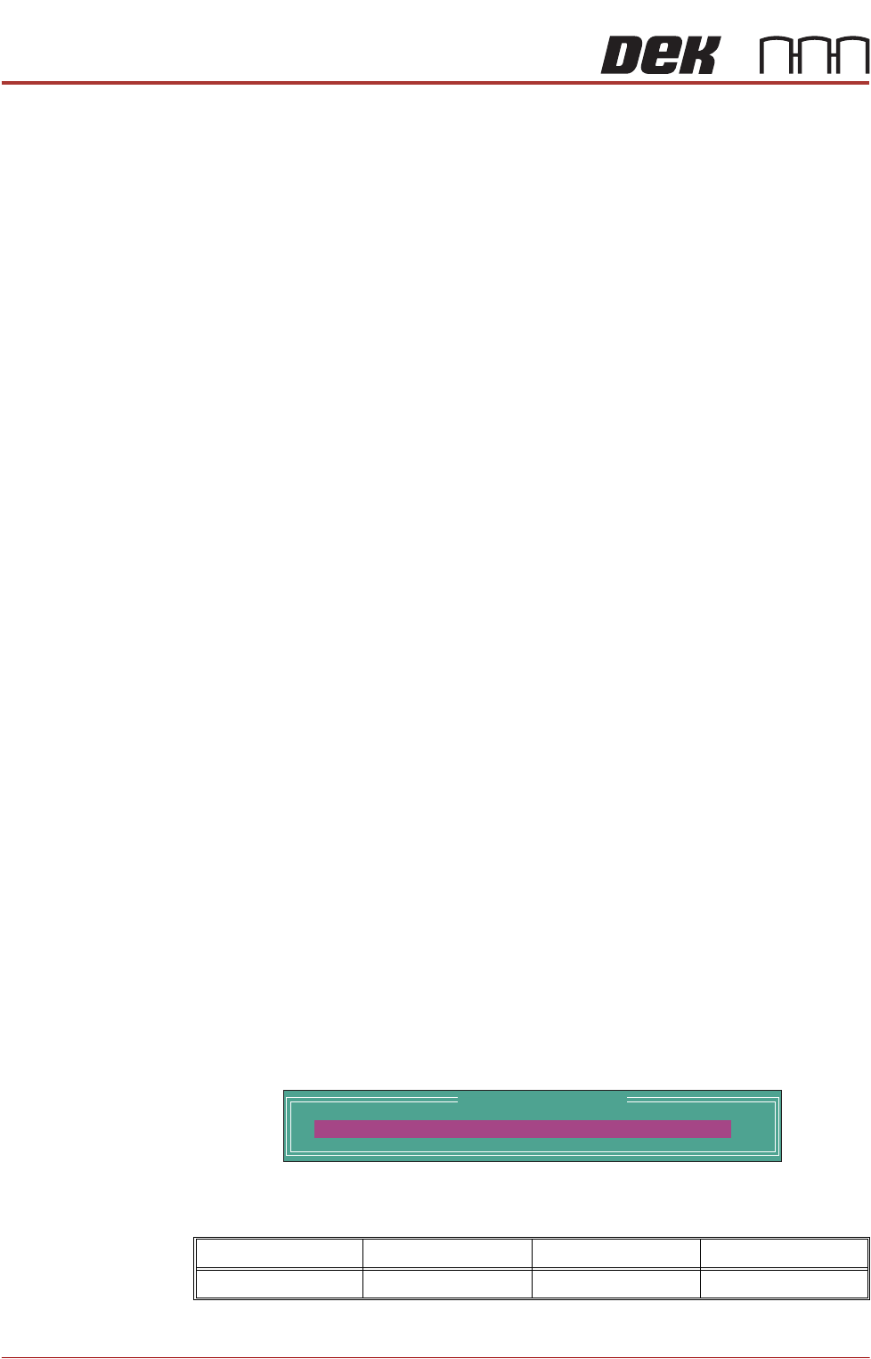
15. Select ProFlow Heights.
The following window is displayed:
The ProFlow contact position sets the height of the ProFlow printhead so
that it just touches the stencil surface.
Minimum Maximum Increment Default
- 10mm +10mm 0.1mm 0.0mm
ProFlow Calibrations
PFLOW CONTACT POS.
0.0
mm