88192278-01-19 Installation Master.pdf - 第187页
POWER UP SEQUENCE MACHINE POWER UP SEQU ENCE Chapter Issue 10, Nov 19 Installation Manual 5.11 16. U sing the Incr . or Decr. but tons, set the ProFlow contact position to 5.5mm . 17. Select Move to Position , the ProFlo…
POWER UP SEQUENCE
MACHINE POWER UP SEQUENCE
5.10 Installation Manual Chapter Issue 10, Nov 19
9. Ensure that the Paste Cartridge Empty is displaying OFF.
10. Paste consistency varies throughout the cartridge, ensure the sensor can
detect paste throughout the length of the cartridge without the Paste Car-
tridge Empty switching to ON.
NOTE
If adjustment of the paste level sensor is required, refer to the Technical
Reference manual - Paste Dispenser System - Adjustments and Settings
section.
11. Close printhead cover.
12. Press the System button.
13. Select Exit.
14. Select Exit.
15. Select Back.
ProFlow Contact
Position Setup
For machines using ProFlow only, set up the contact height position as follows:
1. Select Open Cover Commands.
2. Select Carriage To Front.
3. Open the printhead cover.
4. Load the calibration screen into the chase.
5. Fit an empty transfer head to the ProFlow pressure mechanism and remove
the ProFlow cover.
6. Position a 0.1mm shim on the stencil under the transfer head.
7. Close the printhead cover.
8. Press the System button.
9. Select Back.
10. Select Load Screen.
11. Select Maintenance.
12. Select Calibrations.
13. Select Classic Calibrations.
14. Select ProFlow.
15. Select ProFlow Heights.
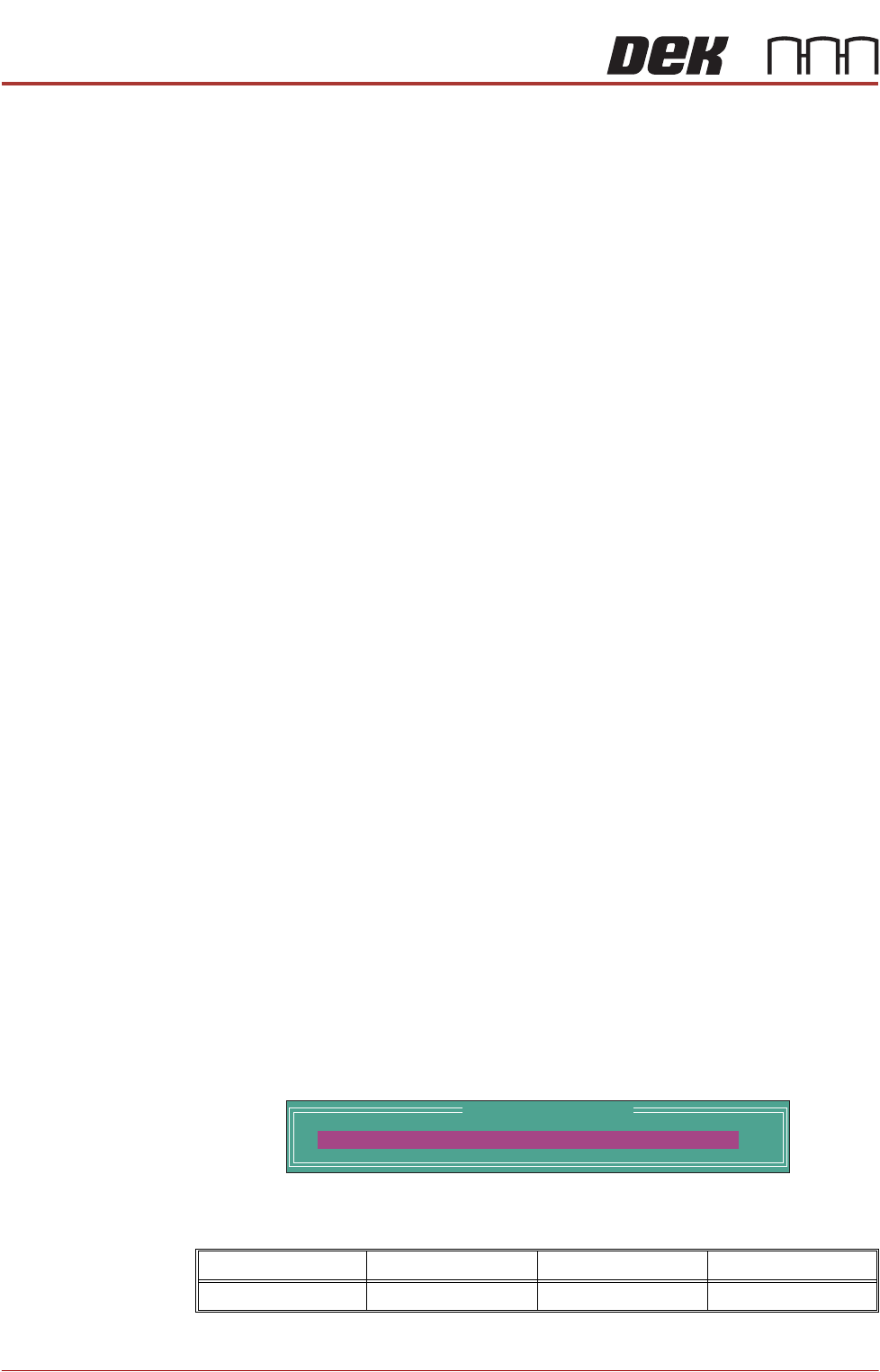
The following window is displayed:
The ProFlow contact position sets the height of the ProFlow printhead so
that it just touches the stencil surface.
Minimum Maximum Increment Default
- 10mm +10mm 0.1mm 0.0mm
ProFlow Calibrations
PFLOW CONTACT POS.
0.0
mm

POWER UP SEQUENCE
MACHINE POWER UP SEQUENCE
Chapter Issue 10, Nov 19 Installation Manual 5.11
16. Using the Incr. or Decr. buttons, set the ProFlow contact position to 5.5mm.
17. Select Move to Position, the ProFlow unit is driven to the position set.
18. Open the printhead cover.
NOTE
Correct contact height is when the shim is just held between the transfer
head wipers and stencil. At this position it is not possible to slide the shim
sideways past the transfer head skis.
19. If correct contact height is achieved go to Step 25.
20. Close the printhead cover.
21. Press the System button.
22. Using the Incr. or Decr. buttons, increase or decrease the Contact Position
set height by 0.5mm (eg 5.0mm or 6.0mm).
NOTE
Normally the contact position is between 4mm and 8mm (nominally 6mm).
23. Select Move to Position, the ProFlow unit is driven to the position set.
24. Repeat steps 18 and 19.
25. Close the printhead cover.
26. Press the System button.
27. Select Exit.
28. Select Exit.
29. Select Exit.
30. Select Back.
31. Select Back.
32. Select Unload Screen.
33. Open the printhead cover.
34. Remove the shim
35. Remove empty transfer head.
36. Remove calibration screen.
37. Close the printhead cover.
38. Press the System button.
POWER UP SEQUENCE
MACHINE POWER UP SEQUENCE
5.12 Installation Manual Chapter Issue 10, Nov 19
Vision System
Calibration
NOTE
Carry out the vision system two stage calibrations for scale and offset in the
Camera Module Chapter of the Technical Reference Manual.
Fitting the
Handheld Barcode
Reader
1. Select Shut Down and switch the mains isolator to OFF.
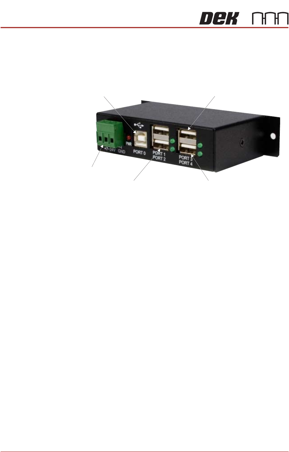
2. Gain access to the 4 port USB hub behind the front panel.
3. Connect the handheld barcode reader to a spare USB port on the hub.
4. Refit the front cover ensuring that the cable is routed between the MMI
monitor bracket and the front cover.
5. Power up the machine.
6. Select Maintenance.
7. Select Machine Setup.
8. Select Barcodes.
9. Select Remote Barcode HW.
10. Select Fitted.
11. Select Accept.
12. Select Data Comms.
13. Select Serial Ports if the COM Port is known proceed to Step 21.
14. Select Device Manager.
NOTE
This opens the device manager window on the PC.
15. Expand Ports.
16. Note the Com Port Number for the Handheld Barcode Reader (e.g. Datalo-
ger COM8)
17. Close the Device Manager.
18. Select Handheld Barcode Reader.
19. Set the port number (e.g. 8)
20. Select Accept.
21. Select Enable Handheld.
22. Select Back
From PC
From M37
Touchscreen Monitor IR Receiver/Keyboard
Extension USB