88192278-01-19 Installation Master.pdf - 第188页
POWER UP SEQUENCE MACHINE POWER UP SEQUENCE 5.12 Installation Manual Chapter Issue 10, Nov 19 Vision Syste m Calibration NOTE Carry out the vision system two stag e calibrations for scale and offset in the Camera Module …

POWER UP SEQUENCE
MACHINE POWER UP SEQUENCE
Chapter Issue 10, Nov 19 Installation Manual 5.11
16. Using the Incr. or Decr. buttons, set the ProFlow contact position to 5.5mm.
17. Select Move to Position, the ProFlow unit is driven to the position set.
18. Open the printhead cover.
NOTE
Correct contact height is when the shim is just held between the transfer
head wipers and stencil. At this position it is not possible to slide the shim
sideways past the transfer head skis.
19. If correct contact height is achieved go to Step 25.
20. Close the printhead cover.
21. Press the System button.
22. Using the Incr. or Decr. buttons, increase or decrease the Contact Position
set height by 0.5mm (eg 5.0mm or 6.0mm).
NOTE
Normally the contact position is between 4mm and 8mm (nominally 6mm).
23. Select Move to Position, the ProFlow unit is driven to the position set.
24. Repeat steps 18 and 19.
25. Close the printhead cover.
26. Press the System button.
27. Select Exit.
28. Select Exit.
29. Select Exit.
30. Select Back.
31. Select Back.
32. Select Unload Screen.
33. Open the printhead cover.
34. Remove the shim
35. Remove empty transfer head.
36. Remove calibration screen.
37. Close the printhead cover.
38. Press the System button.
POWER UP SEQUENCE
MACHINE POWER UP SEQUENCE
5.12 Installation Manual Chapter Issue 10, Nov 19
Vision System
Calibration
NOTE
Carry out the vision system two stage calibrations for scale and offset in the
Camera Module Chapter of the Technical Reference Manual.
Fitting the
Handheld Barcode
Reader
1. Select Shut Down and switch the mains isolator to OFF.
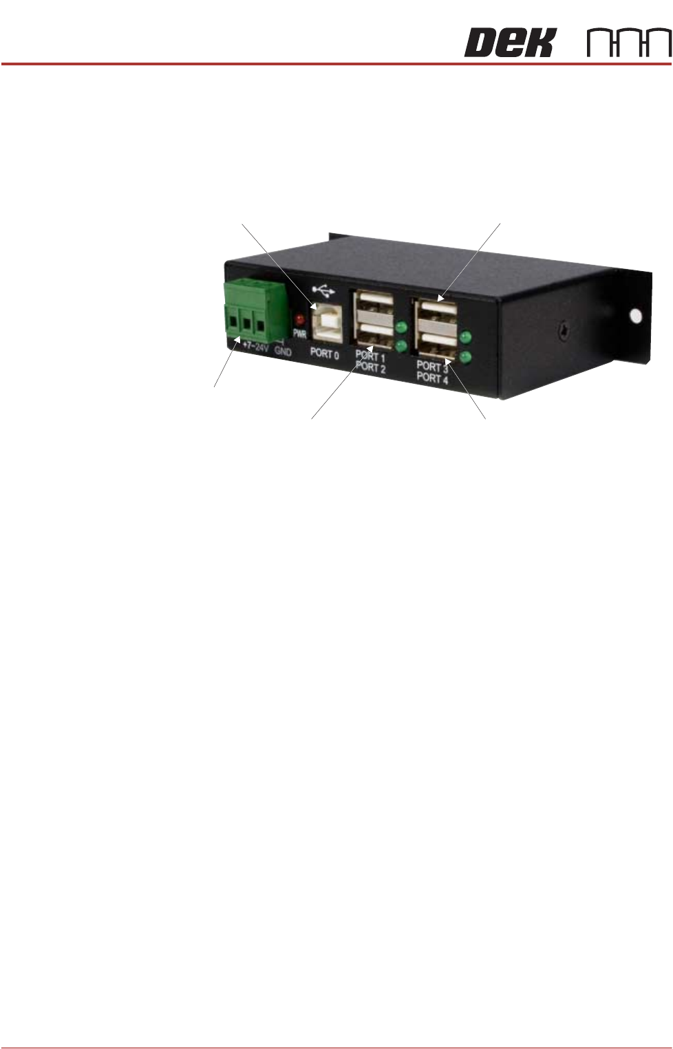
2. Gain access to the 4 port USB hub behind the front panel.
3. Connect the handheld barcode reader to a spare USB port on the hub.
4. Refit the front cover ensuring that the cable is routed between the MMI
monitor bracket and the front cover.
5. Power up the machine.
6. Select Maintenance.
7. Select Machine Setup.
8. Select Barcodes.
9. Select Remote Barcode HW.
10. Select Fitted.
11. Select Accept.
12. Select Data Comms.
13. Select Serial Ports if the COM Port is known proceed to Step 21.
14. Select Device Manager.
NOTE
This opens the device manager window on the PC.
15. Expand Ports.
16. Note the Com Port Number for the Handheld Barcode Reader (e.g. Datalo-
ger COM8)
17. Close the Device Manager.
18. Select Handheld Barcode Reader.
19. Set the port number (e.g. 8)
20. Select Accept.
21. Select Enable Handheld.
22. Select Back
From PC
From M37
Touchscreen Monitor IR Receiver/Keyboard
Extension USB

POWER UP SEQUENCE
MACHINE POWER UP SEQUENCE
Chapter Issue 10, Nov 19 Installation Manual 5.13
23. Select Back
24. Select Back
25. Select Barcodes.
26. Use the documentation supplied with the reader to setup the language,
keyboard format and barcode symbolism.
Configuring the
Handheld Barcode
Reader
To configure the handheld barcode reader:
1. Using the Manufacturer’s Quick Reference Guide, find the page with the
barcodes.
2. Using the barcode reader, scan the barcode entitled: USB COM Emulation.
The unit emits a beep, the LED turns green.
Testing the
Handheld Barcode
Reader
To test the handheld barcode reader:
1. Open Notepad software from the machines Windows Start Menu.
2. Using the barcode reader, scan an example barcode from the Manufac-
turer’s Quick Reference Guide.
3. If Notepad displays barcode content as expected, then the handheld bar-
code reader is working correctly.
If the barcode read is unsuccessful, see the Troubleshooting section below.
Troubleshooting If the barcode read is unsuccessful, try the following:
1. Check all physical connections of the hardware (barcode reader, cables/
looms etc).
2. Re-configure the barcode reader and re-test.
3. Check troubleshooting information in barcode reader’s Manufacturer’s
handbook(s).
4. Escalate the issue to ASM Customer Support.