88192278-01-19 Installation Master.pdf - 第191页
HIGH THROUGHPUT CONVEYOR (HTC) INTRODUCTION Chapter Issue 6, May 20 Installation Manual 6.1 CHAPTER 6 HIGH THROUGH PUT CONVEYOR (HTC) INTRODUCTION Figure 6-1 HTC Controller Location The HTC controller (M27) enclosure is …

POWER UP SEQUENCE
MACHINE POWER UP SEQUENCE
5.14 Installation Manual Chapter Issue 10, Nov 19
HIGH THROUGHPUT CONVEYOR (HTC)
INTRODUCTION
Chapter Issue 6, May 20 Installation Manual 6.1
CHAPTER 6 HIGH THROUGHPUT CONVEYOR (HTC)
INTRODUCTION
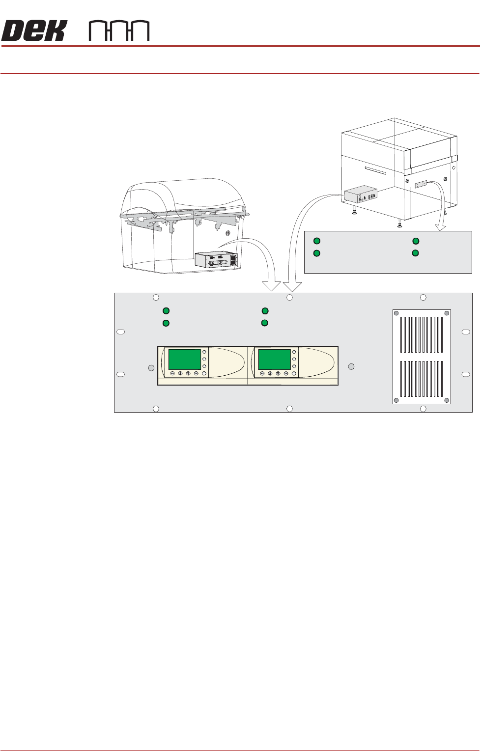
Figure 6-1 HTC Controller Location
The HTC controller (M27) enclosure is located behind the front maintenance
cover just below the mains isolator switch.
On Gemini and NeoHorizon printers the HTC controller (M27) enclosure is
located at the rear. For ease of access a remote switch panel is located behind
the front maintenance cover.
The M27 consists of a Programmable Logic Controller (PLC) for each auxiliary
conveyor. Above each PLC are the switches for selecting between 3-stage/
single stage and fast/normal mode.
On machine initialisation, each auxiliary conveyor PLC needs to detect the
machine ‘System Power’ and a ‘Downline Available’ signal before the system
starts operating. If the machine is being run in a stand-alone environment, the
‘Downline Available’ signal from the downline machine can be mimicked by
shorting pins 1 & 2 of loom Pt No 88160645-01 to the downline machine.
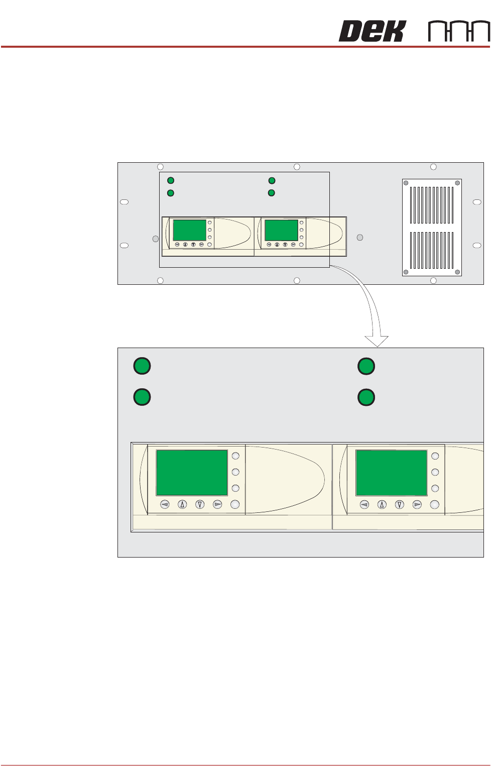
1/3 STAGE
OPERATION
1/3 STAGE
OPERATION
FAST TRANSFERS
DISABLED
FAST TRANSFERS
DISABLED
1/3 STAGE
OPERATION
1/3 STAGE
OPERATION
FAST TRANSFERS
DISABLED
FAST TRANSFERS
DISABLED
R/H CONVEYOR L/H CONVEYOR
ESC
OK
+
-
ESC
OK
+
-
Remote Switch Panel
R/H CONVEYOR L/H CONVEYOR
HIGH THROUGHPUT CONVEYOR (HTC)
OPERATION
6.2 Installation Manual Chapter Issue 6, May 20
OPERATION The 1/3 Stage Operation and Fast Transfers Disabled buttons are LED illumi-
nated push buttons and are configured as follows:
3-Stage/Single
Stage Mode
For 3-stage mode, both 1/3 Stage Operation buttons must be OFF (LED
extinguished). The LCD screen on the PLC displays ‘3 Stage’ on the top line.
For single stage mode, both 1/3 Stage Operation buttons must be ON (LED
lit).The LCD screen on the PLC displays ‘1 Stage’ on the top line.
Fast/Normal Mode For a conveyor to operate in fast transfer mode, both Fast Transfer Disabled
buttons must be OFF (LED extinguished). The LCD screen on the PLC displays
‘Fst.Trans.’ on the bottom line for 5 seconds on power-up or when the button
is switched to OFF.
For a conveyor to operate in normal transfer mode, both Fast Transfer Disabled
buttons must be ON (LED lit). Normal transfer mode is not displayed on the
PLC.
1/3 STAGE
OPERATION
1/3 STAGE
OPERATION
FAST TRANSFERS
DISABLED
FAST TRANSFERS
DISABLED
R/H CONVEYOR L/H CONVEYOR
1/3 STAGE
OPERATION
1/3 STAGE
OPERATION
FAST TRANSFERS
DISABLED
FAST TRANSFERS
DISABLED
R/H CONVEYOR L/H CONVEYOR
ESC
OK
+
-
ESC
OK
+
-
ESC
OK
+
-
ESC
OK
+
-