88192278-01-19 Installation Master.pdf - 第201页
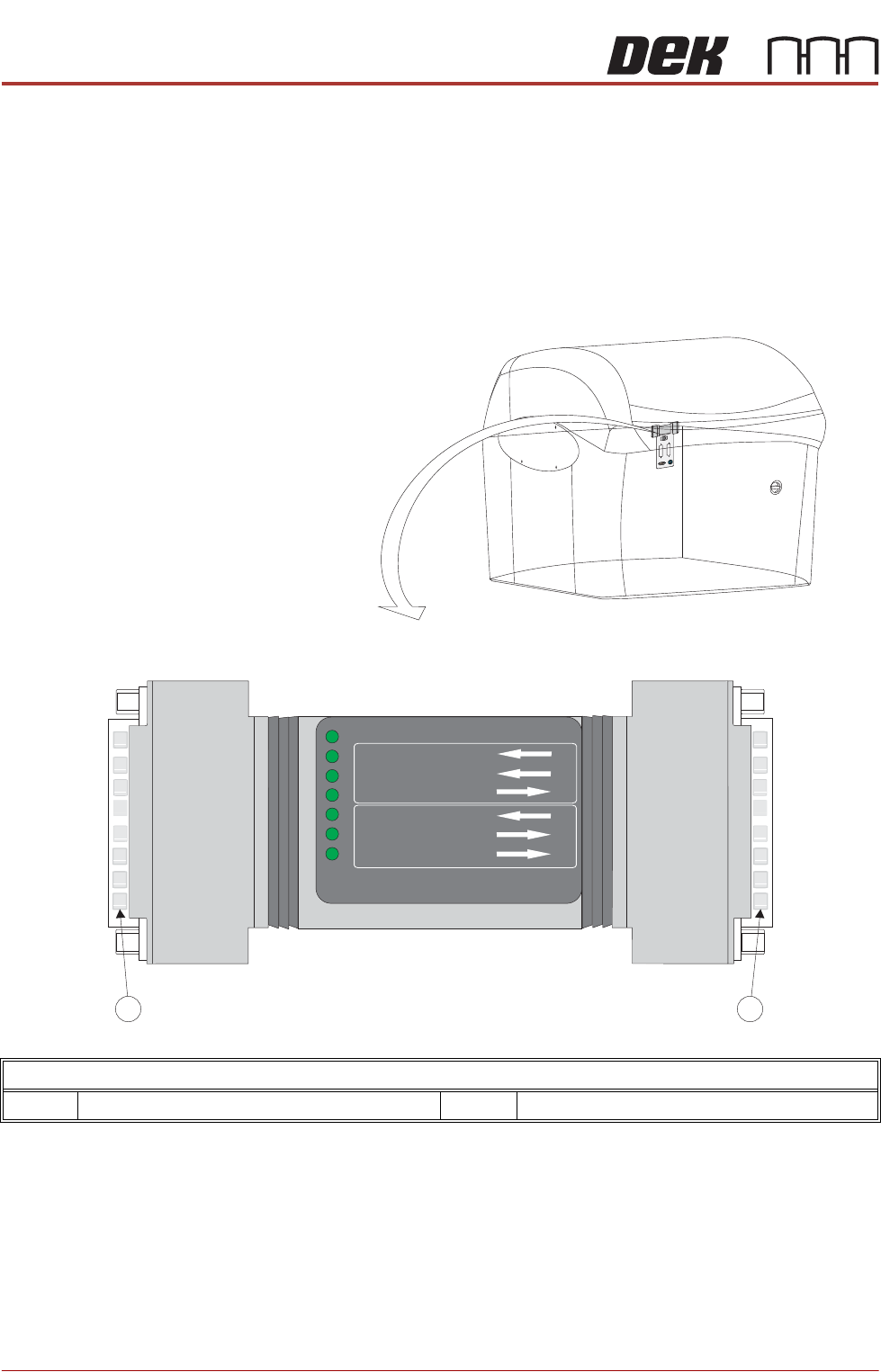
FOREIGN MACHINE INTERFACE MULTI-INTERFACE UNIT Chapter Issue 7. May 20 Installation Manual 7.3 MUL TI-INTERF ACE UNIT The DEK Multi-Interface Unit (MIU) is a communications interface that allows DEK Printing Machines to …
FOREIGN MACHINE INTERFACE
FMI POD
7.2 Installation Manual Chapter Issue 7. May 20
FMI POD The FMI Pod is only used where both the upline and downline is using SMEMA,
Fuji or Panasonic interfaces. For all other interfaces refer to the MIU interface
later in this chapter.
The DEK FMI Pod, located on the external services panel at the rear of the
machine, is a communications interface that allows DEK Printing Machines to
communicate with upline and downline board handlers.
NOTE
The FMI Pod is located at the front of Type 4 machines and accessed by
removing the front panel.
FMI POD Location and Connectors
1 M28SK02 Connector 2 M28PL01 Connector (to M36SK04)

FOREIGN MACHINE INTERFACE
MULTI-INTERFACE UNIT
Chapter Issue 7. May 20 Installation Manual 7.3
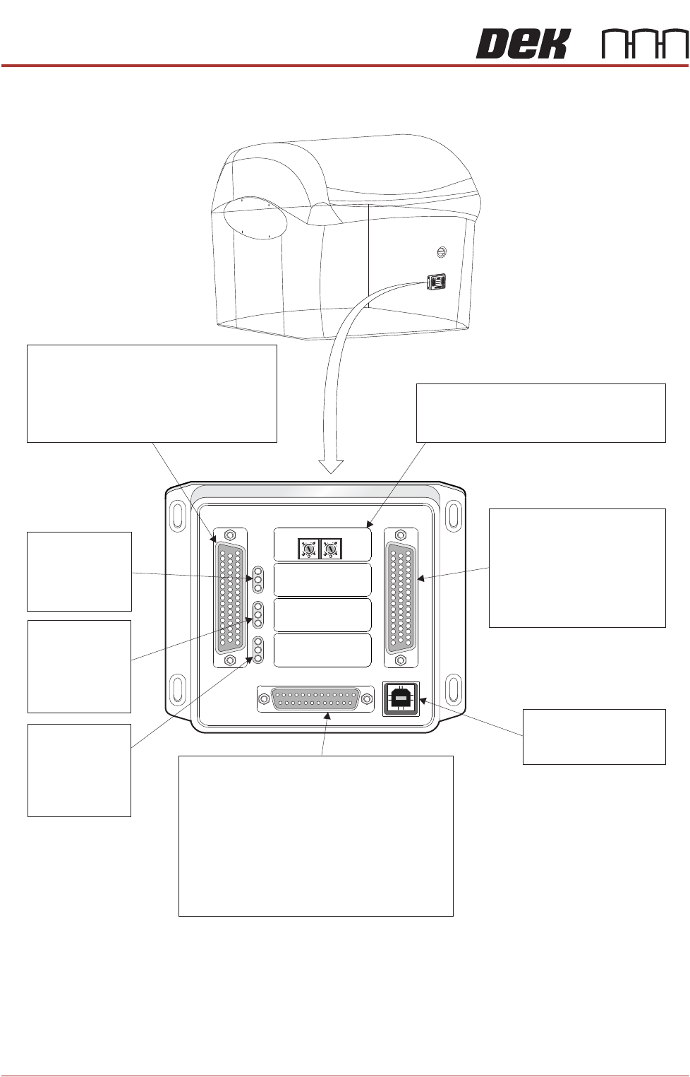
MULTI-INTERFACE UNIT
The DEK Multi-Interface Unit (MIU) is a communications interface that allows
DEK Printing Machines to communicate with upline and downline board han-
dlers.
It simplifies the set up of the communications link between machines of different
manufacture by providing pre programmed and programmable connections to
suit the interface protocol types commonly found within the board processing
industry.
The onboard, switch selectable, interface types are detailed later in this section.
Up to 16 interfaces can be specified for upline and downline handlers. The
upline machine can be of a different interface type to the downline machine.
Power supplies of +24V and +12V power the communications devices of the
upline and downline machines. Input signals to the MIU are opto-isolated. Relay
or open collector output driver signals are available for the MIU outputs.
A patching area routes patching link connections direct from upline to downline
as specified by any given protocol requirement.
FOREIGN MACHINE INTERFACE
MULTI-INTERFACE UNIT
7.4 Installation Manual Chapter Issue 7. May 20
Figure 7-1 Multi-Interface Unit
M1SK1
UPLINE
M1SK2
DOWNLINE
M1PL3
DEK M/C
M1SK4
DEK USB
+12V
+24V
+24V SW
SEND UPLINE
SEND DOWNLINE
CONTROL IN
UPLINE READY
DOWNLINE READY
CONTROL OUT
POWER
I/P'S
O/P'S
PROTOCOL SELECTION
UP
LINE
DOWN
LINE
MIU 191114
Protocol Selection
Upline interface select switch.
Downline interface select switch.
M1SK1
Signal lines to and from the DEK machine
from the upline machine.
4 Inputs: Opto-isolated.
4 Outputs: Lowside driver.
4 Outputs: Solid State Relay switched.
LED Bank LD1
Shows the
integrity of
the derived
supplies
LED Bank LD2
Indicates the
sequence of
events during
board transfers
(Inputs)
LED Bank LD3
Indicates the
sequence of
events during
board transfers
(Outputs)
M1SK2
Signal lines to and from
the DEK machine from
the downline machine.
4 Inputs: Opto-isolated.
4 Outputs: Lowside driver.
4 Outputs: Solid State
Relay switched.
DEK USB connection
not used.
M1SK4
M
1
S
K
1
M1
S
K
1
U
P
L
I
N
E
U
P
L
I
N
E
M
1
S
K
2
M
1
S
K
2
D
O
W
N
L
I
N
E
D
O
W
N
LI
NE
M
1
P
L
3
M1P
L
3
D
E
K
M
/
C
D
E
K
M/
C
M
1
S
K
4
M1
S
K
4
D
E
K
U
S
B
D
E
K
U
S
B
+
1
2
V
+
12
V
+
2
4
V
+
24V
+
2
4
V
S
W
+24V SW
S
E
N
D
U
P
L
I
N
E
SEND
UPLINE
S
E
N
D
D
O
W
N
L
I
N
E
S
E
ND
D
O
W
NL
IN
E
C
O
N
T
R
O
L
I
N
CONT
R
O
L
IN
U
P
L
I
N
E
R
E
A
D
Y
U
PL
INE
READY
D
O
W
N
L
I
N
E
R
E
A
D
Y
DOWN
LI
NE
REA
D
Y
C
O
N
T
R
O
L
O
U
T
CO
NTR
O
LOUT
P
O
W
E
R
P
O
W
ER
I
/
P
'
S
I
/
P
'S
O
/
P
'
S
O
/
P
'
S
PRO
T
OC
OL
SE
LE
C
T
IO
N
PR
OT
OC
OL
SE
L
E
C
T
I
ON
U
P
U
P
L
I
N
E
L
INE
D
O
W
N
DOWN
L
I
N
E
L
IN
E
M
IU
1
91
114M
I
U 19
1
114
4
8
0
4
8
0
M1PL3
Power supplies.
Comms connections to the DEK machine
Inputs to the DEK machine from interface -
1. Downline Ready
2. Upline Ready
3. Control In
Outputs from the DEK machine to interface -
1. Send Downline
2. Send Upline
3. Control Out
4
80
4
80