88192278-01-19 Installation Master.pdf - 第203页
FOREIGN MACHINE INTERFACE MULTI-INTERFACE UNIT Chapter Issue 7. May 20 Installation Manual 7.5 Protocol Selection Figure 7-2 Interface Selector Switches M1SK1 UP LIN E M1SK2 DOW NLIN E M1P L 3 DEK M/C M1SK4 DEK USB +12V …
FOREIGN MACHINE INTERFACE
MULTI-INTERFACE UNIT
7.4 Installation Manual Chapter Issue 7. May 20
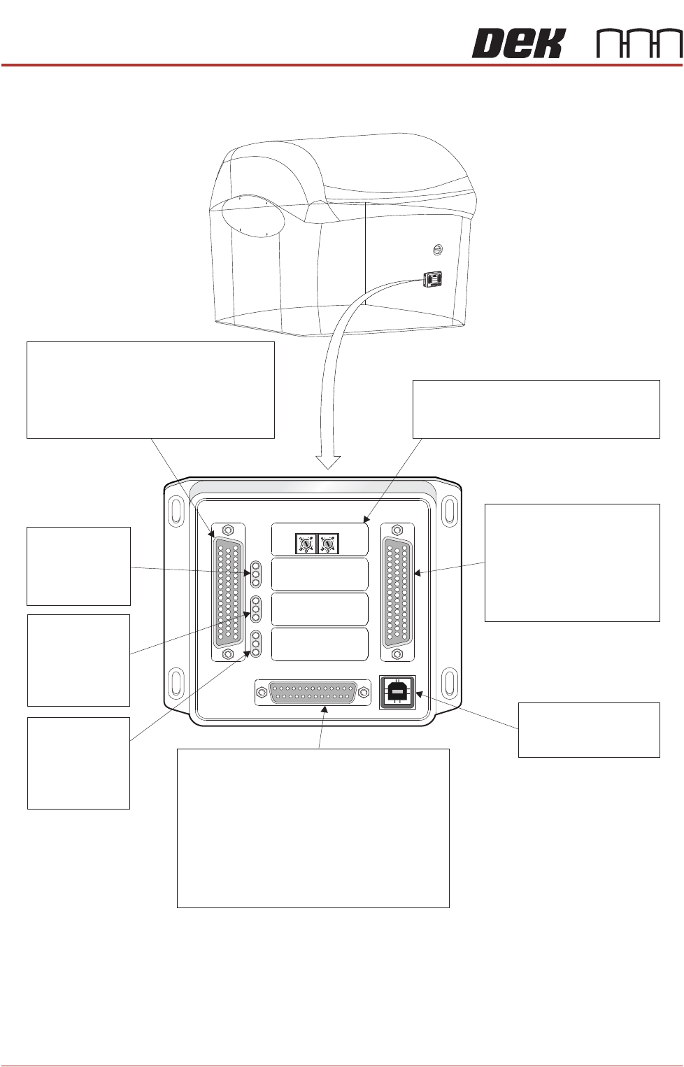
Figure 7-1 Multi-Interface Unit
M1SK1
UPLINE
M1SK2
DOWNLINE
M1PL3
DEK M/C
M1SK4
DEK USB
+12V
+24V
+24V SW
SEND UPLINE
SEND DOWNLINE
CONTROL IN
UPLINE READY
DOWNLINE READY
CONTROL OUT
POWER
I/P'S
O/P'S
PROTOCOL SELECTION
UP
LINE
DOWN
LINE
MIU 191114
Protocol Selection
Upline interface select switch.
Downline interface select switch.
M1SK1
Signal lines to and from the DEK machine
from the upline machine.
4 Inputs: Opto-isolated.
4 Outputs: Lowside driver.
4 Outputs: Solid State Relay switched.
LED Bank LD1
Shows the
integrity of
the derived
supplies
LED Bank LD2
Indicates the
sequence of
events during
board transfers
(Inputs)
LED Bank LD3
Indicates the
sequence of
events during
board transfers
(Outputs)
M1SK2
Signal lines to and from
the DEK machine from
the downline machine.
4 Inputs: Opto-isolated.
4 Outputs: Lowside driver.
4 Outputs: Solid State
Relay switched.
DEK USB connection
not used.
M1SK4
M
1
S
K
1
M1
S
K
1
U
P
L
I
N
E
U
P
L
I
N
E
M
1
S
K
2
M
1
S
K
2
D
O
W
N
L
I
N
E
D
O
W
N
LI
NE
M
1
P
L
3
M1P
L
3
D
E
K
M
/
C
D
E
K
M/
C
M
1
S
K
4
M1
S
K
4
D
E
K
U
S
B
D
E
K
U
S
B
+
1
2
V
+
12
V
+
2
4
V
+
24V
+
2
4
V
S
W
+24V SW
S
E
N
D
U
P
L
I
N
E
SEND
UPLINE
S
E
N
D
D
O
W
N
L
I
N
E
S
E
ND
D
O
W
NL
IN
E
C
O
N
T
R
O
L
I
N
CONT
R
O
L
IN
U
P
L
I
N
E
R
E
A
D
Y
U
PL
INE
READY
D
O
W
N
L
I
N
E
R
E
A
D
Y
DOWN
LI
NE
REA
D
Y
C
O
N
T
R
O
L
O
U
T
CO
NTR
O
LOUT
P
O
W
E
R
P
O
W
ER
I
/
P
'
S
I
/
P
'S
O
/
P
'
S
O
/
P
'
S
PRO
T
OC
OL
SE
LE
C
T
IO
N
PR
OT
OC
OL
SE
L
E
C
T
I
ON
U
P
U
P
L
I
N
E
L
INE
D
O
W
N
DOWN
L
I
N
E
L
IN
E
M
IU
1
91
114M
I
U 19
1
114
4
8
0
4
8
0
M1PL3
Power supplies.
Comms connections to the DEK machine
Inputs to the DEK machine from interface -
1. Downline Ready
2. Upline Ready
3. Control In
Outputs from the DEK machine to interface -
1. Send Downline
2. Send Upline
3. Control Out
4
80
4
80
FOREIGN MACHINE INTERFACE
MULTI-INTERFACE UNIT
Chapter Issue 7. May 20 Installation Manual 7.5
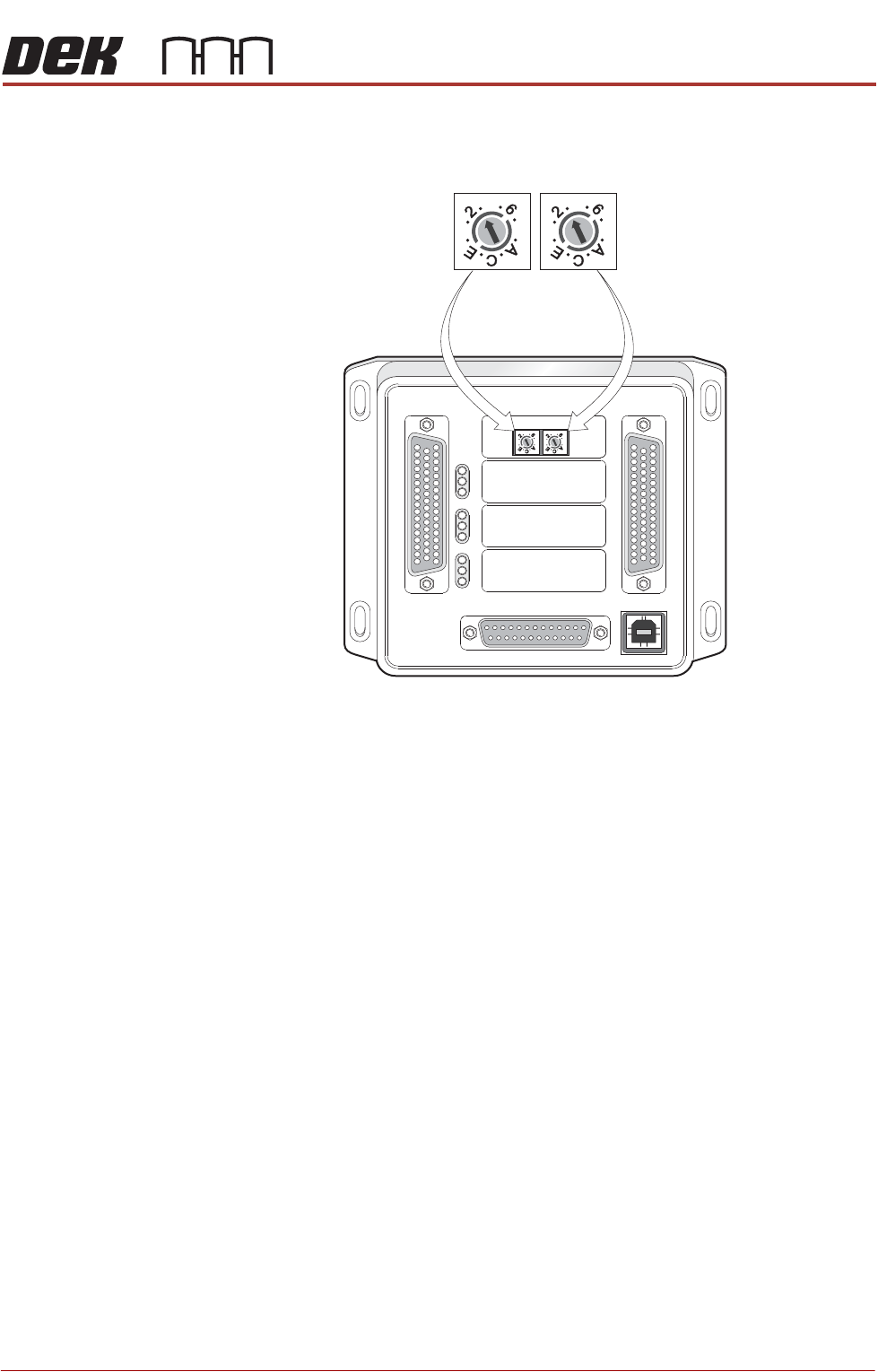
Protocol Selection
Figure 7-2 Interface Selector Switches
M1SK1
UPLINE
M1SK2
DOWNLINE
M1PL3
DEK M/C
M1SK4
DEK USB
+12V
+24V
+24V SW
SEND UPLINE
SEND DOWNLINE
CONTROLIN
UPLINE READY
DOWNLINE READY
CONTROL OUT
POWER
I/P'S
O/P'S
PROTOCOL SELECTION
UP
LINE
DOWN
LINE
MIU 191114
4
80
4
80
4
80
4
80
Upline Interface
Selector Switch (SW2)
Downline Interface
Selector Switch (SW3)

FOREIGN MACHINE INTERFACE
MULTI-INTERFACE UNIT
7.6 Installation Manual Chapter Issue 7. May 20
Part Numbers and Settings
Protocol
MIU Setting Cable Part Number
Upline SW2 Downline SW3 Upline Downline
SMEMA 2 2 88131343-01 88131345-01
Siemens 3 3 88131335-01 88131337-01
SMPI 4 4 88131331-01 88131333-01
TDK 5 5 88131323-01 88131325-01
Fuji 7 7 88126757-01 88126758-01
Panasonic 7 7 88131339-01 88131341-01
Sanyo 8 8 88146120-01 88146119-01