88192278-01-19 Installation Master.pdf - 第208页
FOREIGN MACHINE INTERFAC E DUAL LANE MACHINE 7.10 Installation Manual Chapter Issue 7. May 20
FOREIGN MACHINE INTERFACE
DUAL LANE MACHINE
Chapter Issue 7. May 20 Installation Manual 7.9
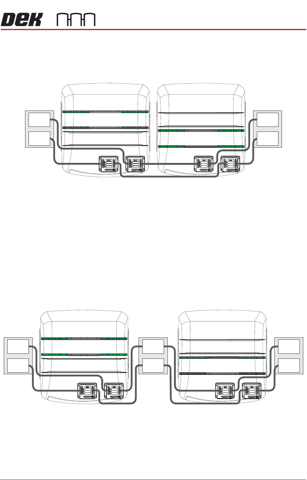
There are many configurations depending on the rules mentioned previously.
Below is an example on how to connect two side-by-side printers to an upline
and a downline machine/conveyor using MIU’s:
NOTE
1. The pass through lane MIU would not be required if the connecting upline
and downline machines use SMEMA, Fuji or Panasonic communications
protocol. Connection would be made to the M40 Dual Lane enclosure.
2. The print lane MIU would be replaced with an FMI pod (located at the rear
of the machine) if the connecting upline and downline machines use
SMEMA, Fuji or Panasonic communications protocol.
Below is an example on how to connect two printers separated by a conveyor,
to an upline and a downline machine/conveyor using MIU’s:
NOTE
The conveyor separating the printers must be considered as the downline
machine to the rear print machine and the upline machine to the front print
machine.
Plan View on Machines
DEK Rear Print Machine
Print Lane
Pass Through Lane
Pass Through Lane
Print Lane
DEK Front Print Machine
M1SK1
UPLINE
M1SK2
DOWNLINE
M1PL3
DEK M/C
M1SK4
DEK USB
+12V
+24V
+24V SW
SEND UPLINE
SEND DOWNLINE
CONTROLIN
UPLINE READY
DOWNLINE READY
CONTROLOUT
POWER
I/P'S
O/P'S
PROTOCOLSELECTION
UP
LINE
DOWN
LINE
MIU 191114
4
80
4
80
M1SK1
UPLINE
M1SK2
DOWNLINE
M1PL3
DEK M/C
M1SK4
DEK USB
+12V
+24V
+24V SW
SEND UPLINE
SEND DOWNLINE
CONTROLIN
UPLINE READY
DOWNLINE READY
CONTROLOUT
POWER
I/P'S
O/P'S
PROTOCOLSELECTION
UP
LINE
DOWN
LINE
MIU 191114
4
80
4
80
M1SK1
UPLINE
M1SK2
DOWNLINE
M1PL3
DEK M/C
M1SK4
DEK USB
+12V
+24V
+24V SW
SEND UPLINE
SEND DOWNLINE
CONTROLIN
UPLINE READY
DOWNLINE READY
CONTROLOUT
POWER
I/P'S
O/P'S
PROTOCOLSELECTION
UP
LINE
DOWN
LINE
MIU 191114
4
80
4
80
M1SK1
UPLINE
M1SK2
DOWNLINE
M1PL3
DEK M/C
M1SK4
DEK USB
+12V
+24V
+24V SW
SEND UPLINE
SEND DOWNLINE
CONTROLIN
UPLINE READY
DOWNLINE READY
CONTROLOUT
POWER
I/P'S
O/P'S
PROTOCOLSELECTION
UP
LINE
DOWN
LINE
MIU 191114
4
80
4
80
Upline
Machine/
Conveyor
Downline
Machine/
Conveyor
Pass Through
Pass Through
Print
Print
Lane 1 Lane 1
Lane 2 Lane 2
Plan View on Machines
DEK Rear Print Machine
Print Lane
Pass Through Lane
Pass Through Lane
Print Lane
DEK Front Print Machine
M1SK1
UPLINE
M1SK2
DOWNLINE
M1PL3
DEK M/C
M1SK4
DEK USB
+12V
+24V
+24V SW
SEND UPLINE
SEND DOWNLINE
CONTROLIN
UPLINE READY
DOWNLINE READY
CONTROLOUT
POWER
I/P'S
O/P'S
PROTOCOLSELECTION
UP
LINE
DOWN
LINE
MIU 191114
4
80
4
80
M1SK1
UPLINE
M1SK2
DOWNLINE
M1PL3
DEK M/C
M1SK4
DEK USB
+12V
+24V
+24V SW
SEND UPLINE
SEND DOWNLINE
CONTROLIN
UPLINE READY
DOWNLINE READY
CONTROLOUT
POWER
I/P'S
O/P'S
PROTOCOLSELECTION
UP
LINE
DOWN
LINE
MIU 191114
4
80
4
80
M1SK1
UPLINE
M1SK2
DOWNLINE
M1PL3
DEK M/C
M1SK4
DEK USB
+12V
+24V
+24V SW
SEND UPLINE
SEND DOWNLINE
CONTROLIN
UPLINE READY
DOWNLINE READY
CONTROLOUT
POWER
I/P'S
O/P'S
PROTOCOLSELECTION
UP
LINE
DOWN
LINE
MIU 191114
4
80
4
80
M1SK1
UPLINE
M1SK2
DOWNLINE
M1PL3
DEK M/C
M1SK4
DEK USB
+12V
+24V
+24V SW
SEND UPLINE
SEND DOWNLINE
CONTROLIN
UPLINE READY
DOWNLINE READY
CONTROLOUT
POWER
I/P'S
O/P'S
PROTOCOLSELECTION
UP
LINE
DOWN
LINE
MIU 191114
4
80
4
80
Upline
Machine/
Conveyor
Downline
Machine/
Conveyor
Pass Through
Pass Through
Print
Print
Conveyor
Lane 1Lane 1 Lane 1
Lane 2Lane 2 Lane 2

FOREIGN MACHINE INTERFACE
DUAL LANE MACHINE
7.10 Installation Manual Chapter Issue 7. May 20

MACHINE PERFORMANCE
MACHINE CAPABILITY
Chapter Issue 8, May 20 Installation Manual 8.1
CHAPTER 8 MACHINE PERFORMANCE
MACHINE CAPABILITY
NOTE
If the machine is Multiple Alignment Singulated (MASS) equipped, Capability
and SPC is to be carried out in accordance with SPC in the MASS Standalone
manual.
Printer Running Load the product file named 265test1 from the hard disk and with an ASM
alignment board loaded ensure that the following parameters are correct:
• Screen - Calibration / Dry Align
• Squeegee - Length to suit board / ProFlow - Empty Transfer Head
• Front & Rear Print Speed - 25mm/sec (squeegees) / 70mm/sec (ProFlow)
• Front & Rear Pressure - 5kg (squeegees) / 3kg (ProFlow)
• ProFlow Paste Pressure - 2.2 bar
• ProFlow Idle Pressure - 0.2 bar (ProFlow with SCAR)
• Separation Speed - 1mm/sec.
• Under Board Clearance - 20mm
• Paste Dispense - 0
• Under Screen Rate - 0
• Transport Mode - Left to Left
• SPC Data Output Rate - Every Cycle
• SPC Data Mode - Disk
• SPC Format - Windows
• SPC Align Inspect Mode - Pre & Post Print
Use nine magnetic tooling pins to fully support the board, apply small amount
of paste or suitable lubricant (enough to lubricate squeegees). Record >100 full
machine cycles and setup QC-Cal program as follows:
1. Select QC Calc.