88192278-01-19 Installation Master.pdf - 第210页
MACHINE PERFORMANCE MACHINE CAPABILITY 8.2 Installation Manual Chapter Issue 8, May 20 2. Select Show QC Calc SPC . 3. Select Report . 4. Select Cpk - Process Capability . 5. Highlight the required dimensions to output a…

MACHINE PERFORMANCE
MACHINE CAPABILITY
Chapter Issue 8, May 20 Installation Manual 8.1
CHAPTER 8 MACHINE PERFORMANCE
MACHINE CAPABILITY
NOTE
If the machine is Multiple Alignment Singulated (MASS) equipped, Capability
and SPC is to be carried out in accordance with SPC in the MASS Standalone
manual.
Printer Running Load the product file named 265test1 from the hard disk and with an ASM
alignment board loaded ensure that the following parameters are correct:
• Screen - Calibration / Dry Align
• Squeegee - Length to suit board / ProFlow - Empty Transfer Head
• Front & Rear Print Speed - 25mm/sec (squeegees) / 70mm/sec (ProFlow)
• Front & Rear Pressure - 5kg (squeegees) / 3kg (ProFlow)
• ProFlow Paste Pressure - 2.2 bar
• ProFlow Idle Pressure - 0.2 bar (ProFlow with SCAR)
• Separation Speed - 1mm/sec.
• Under Board Clearance - 20mm
• Paste Dispense - 0
• Under Screen Rate - 0
• Transport Mode - Left to Left
• SPC Data Output Rate - Every Cycle
• SPC Data Mode - Disk
• SPC Format - Windows
• SPC Align Inspect Mode - Pre & Post Print
Use nine magnetic tooling pins to fully support the board, apply small amount
of paste or suitable lubricant (enough to lubricate squeegees). Record >100 full
machine cycles and setup QC-Cal program as follows:
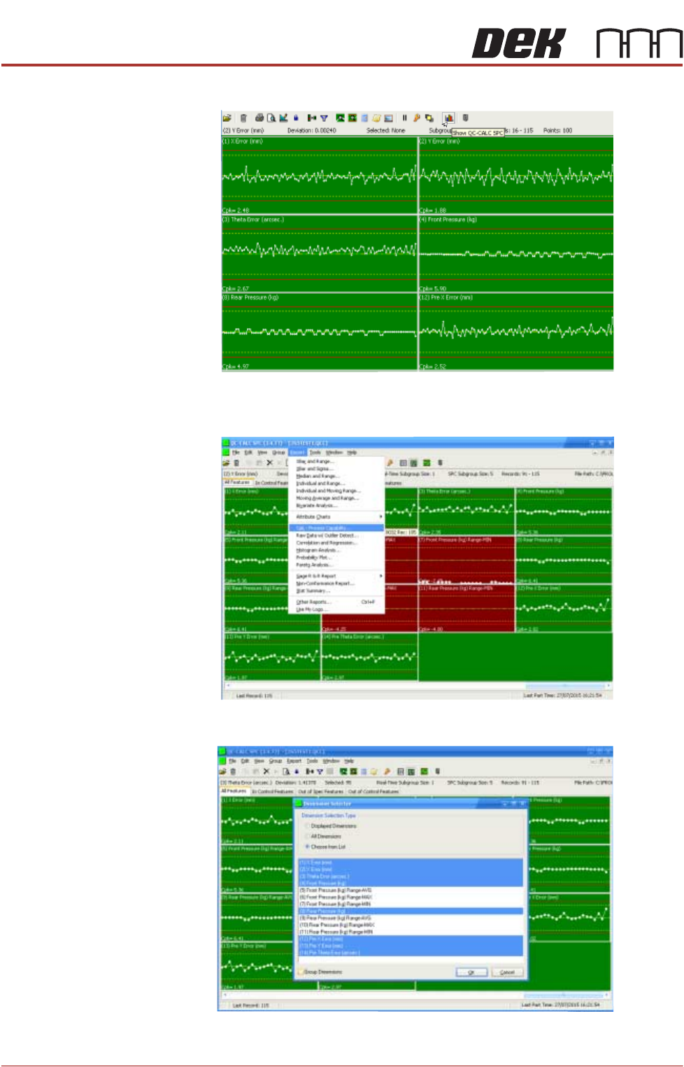
1. Select QC Calc.
MACHINE PERFORMANCE
MACHINE CAPABILITY
8.2 Installation Manual Chapter Issue 8, May 20
2. Select Show QC Calc SPC.
3. Select Report.
4. Select Cpk - Process Capability.
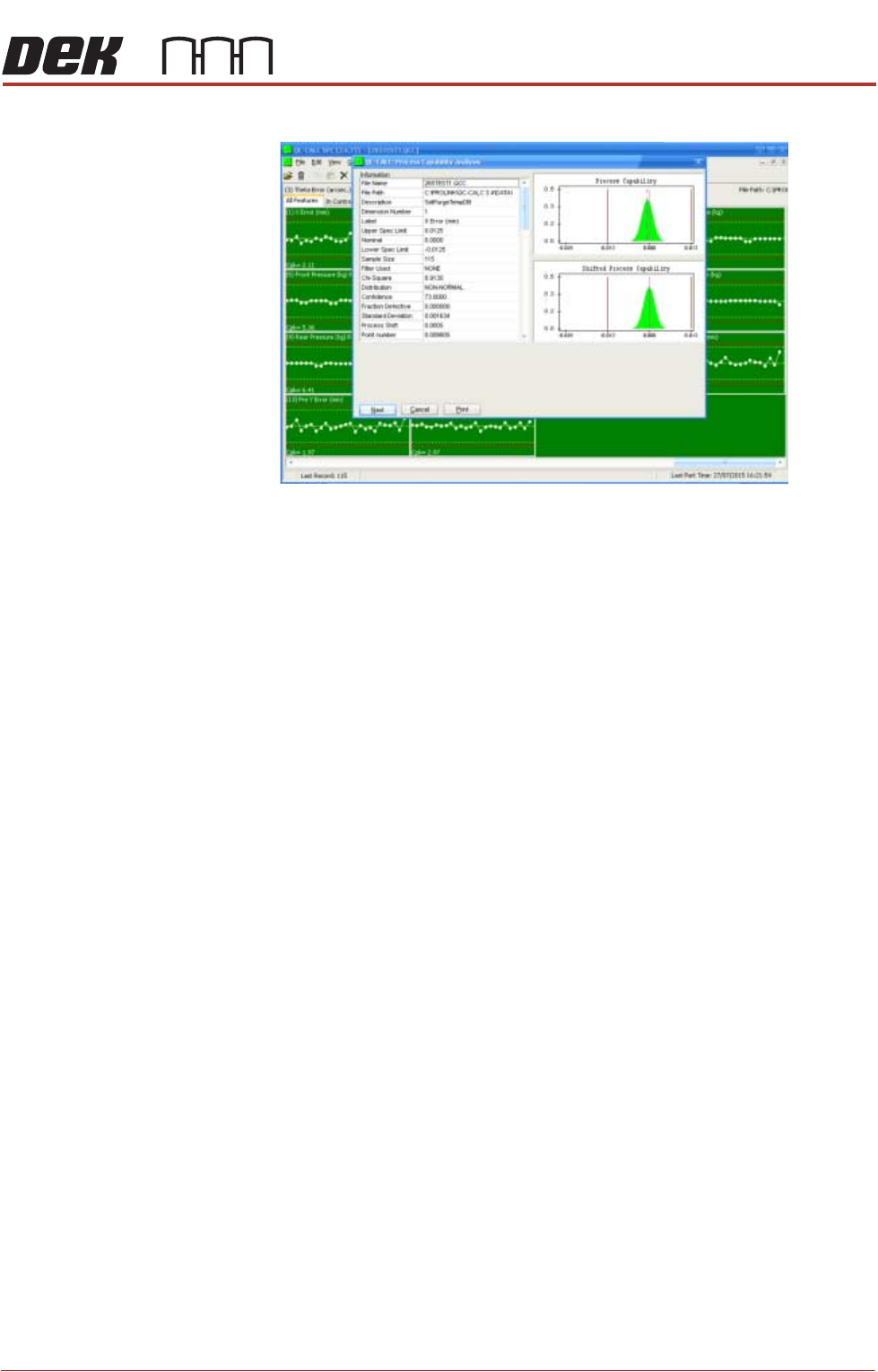
5. Highlight the required dimensions to output and select OK.
6. View the Cp/Cpk values for the dimension illustrated ensuring the values are
MACHINE PERFORMANCE
MACHINE CAPABILITY
Chapter Issue 8, May 20 Installation Manual 8.3
within the specification. Select Next to view the further dimensions.