88192278-01-19 Installation Master.pdf - 第28页
SAFETY FEATURES PRINTHEAD COVER 1.16 Installation Manual Chapter Issue 15, Nov 19 PRINTHEAD COVER Safety Interlocks The safety featu res designed into the printer are fo r the protection of all operators and maintenance …

SAFETY FEATURES
GENERAL
Chapter Issue 15, Nov 19 Installation Manual 1.15
Jog Buttons The two button control switches or jog buttons are positioned such as to
maintain maximum safety for the operator whilst solvent priming or paper
feeding with the printhead cover open. This requires both buttons to be
depressed simultaneously for the function to become active. The use of these
buttons is dependent on the function selected on the printer monitor. During
normal operation these buttons control paper feed and solvent prime opera-
tions. When in maintenance mode, the two button control switches control the
movement of the following diagnostics:
• Print Carriage
• Squeegee Assembly
• Camera Axes
• Rail System
• Stencil Alignment
• Rising Table
• ProFlow
• Paste Dispenser
Only one button is required to drive the selected mechanism, the two buttons
are used to drive the mechanism in opposite directions, ie jog forward or jog
back.

SAFETY FEATURES
PRINTHEAD COVER
1.16 Installation Manual Chapter Issue 15, Nov 19
PRINTHEAD COVER
Safety Interlocks The safety features designed into the printer are for the protection of all
operators and maintenance personnel. ASM strongly recommend safety
devices are never overridden.
Opening the printhead cover allows access to the following areas:
• Printhead
• Paste Dispenser
• Squeegee/ProFlow
• Stencil/Screen
• Under Screen Cleaner
• Tooling
The printhead cover is accessible to the operator and an interlock safety switch
protects personnel from the mechanisms during normal line operations. Lifting
the cover cuts power to all motors and selected actuators, via the E Stop
module, to all printer modules.
Full details of the device types fitted can be found in the covers chapter of this
manual.
NOTE
The pass through lane belt motors on the dual lane printer continue running
when the printhead cover is open but stop when the E Stop is pressed.
Pneumatically operated lid bolt(s) prevents the cover being raised during the
print cycle. The lid bolt is withdrawn and the cover may be raised:
• When Open Cover is requested by software
• When pause or stop is selected during a print cycle
• When the E Stop is pressed
Recovery When the printhead cover is closed, normal working condition is restored and
the line may be restarted. Pressing the system button enables resumption of
operations, where this is allowed by the control system.
SAFETY FEATURES
HIGH VOLTAGE PROTECTION
Chapter Issue 15, Nov 19 Installation Manual 1.17
HIGH VOLTAGE PROTECTION
Access Where incoming supply voltages are present, protection is afforded by con-
trolling access to the enclosures that house the supply. The printer is fitted with
a mains isolator switch that cuts power to all circuits located beyond the switch.
Hazard Warning
Labels
Hazard warning labels are placed on the outside of enclosures where danger-
ous voltage (115V-230V a.c 50-60Hz) terminations are present within.
Earth Bonding All external metal surfaces are mechanically and electrically bonded to the
printer’s protected earth point. The bonding wire used is identified by its green
and yellow insulation and is commonly used to earth bond throughout. Care
should be taken when removing these links that when they are replaced they
are secured tightly and cleanly.
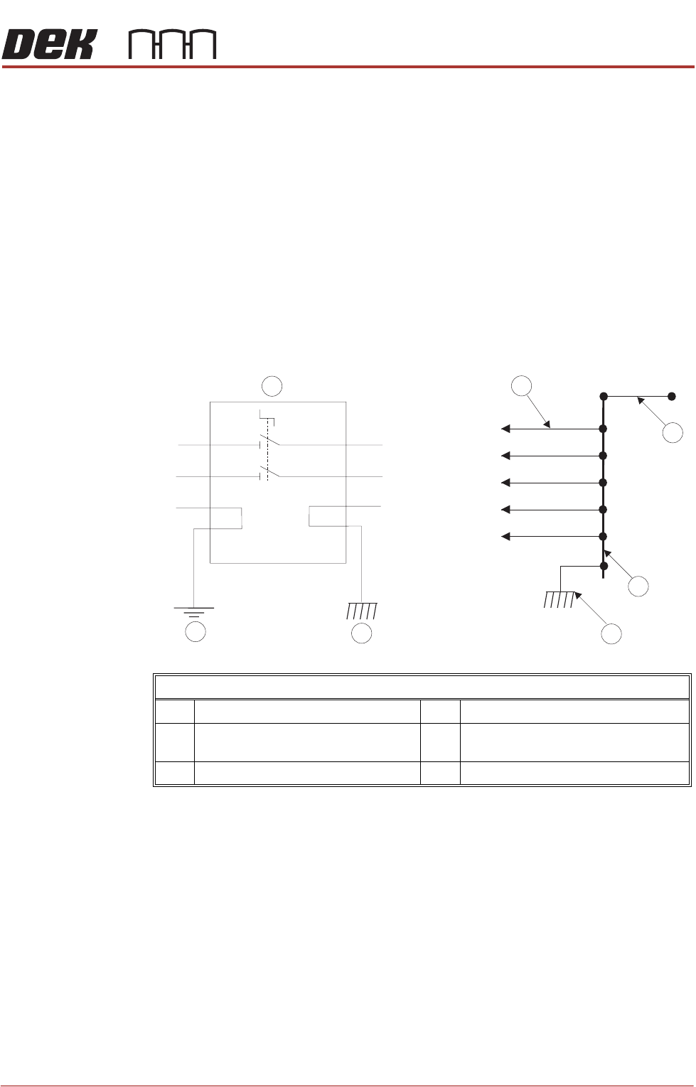
Printer Protected Earth Point
1 PSU M37 Module Earth Bond Stud 4 Printer Protective Earth Chassis Stud
2 Earth Busbar 5 Earth Busbar Connected to Printer
Frame
3 Printer Bonding Earth Chassis Stud 6 Printer Earth Connections