88192278-01-19 Installation Master.pdf - 第42页
COVERS PRINTER COVERS 2.8 Installation Manual Chapter Issue 12, Feb 18 5. Insert the switch release tool (Part No 188647) into the slots and push until the release tool clicks into place. 6. Leaving the switch release to…
COVERS
PRINTER COVERS
Chapter Issue 12, Feb 18 Installation Manual 2.7
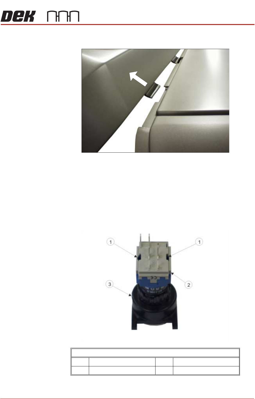
4. Once the locating tabs have cleared, pull the cover horizontally away from
the printer.
Upper Side Panels To remove the upper side panels, carry out the following:
1. Remove the rear printhead fixed cover (as detailed previously).
2. Open the front printhead cover.
3. Remove the corresponding safety cover (as detailed previously).
NOTE
Before the upper side panel can be removed, the control switches (system
switch, jog switch etc.) must be disconnected in the following manner.
4. Locate the two release slots in the contact assembly part of the switch.
View on Rear of Switch
1 Release Slot 3 Switch Body
2 Contact Assembly
COVERS
PRINTER COVERS
2.8 Installation Manual Chapter Issue 12, Feb 18
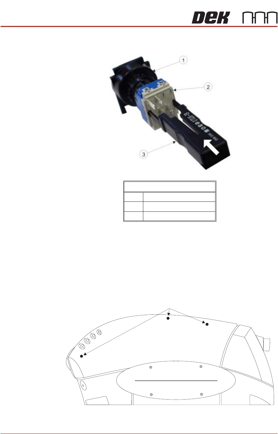
5. Insert the switch release tool (Part No 188647) into the slots and push until
the release tool clicks into place.
6. Leaving the switch release tool in position, pull the contact assembly from
the switch body.
7. Remove the switch release tool from the contact assembly.
NOTE
To refit the contact assembly to the switch body, using the locating keyway,
push the two units together until they click into place.
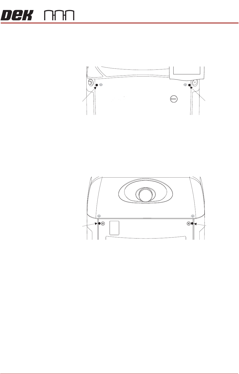
8. Release the three quarter-turn fasteners that secure the upper side panel
and remove the panel.
9. Repeat Steps 3 to 8 for the other side panel, if required.
View on Rear of Switch
1 Switch Body
2 Contact Assembly
3 Switch Release Tool
Upper Side Panel Quarter-Turn Fasteners
COVERS
PRINTER COVERS
Chapter Issue 12, Feb 18 Installation Manual 2.9
Front Corner Panels To remove the front corner panels, carry out the following:
1. Remove the front panel.
2. Remove the corresponding upper side panel (as detailed previously).
3. Release the quarter-turn fastener that secures the corner panel.
4. Lift the corner panel upwards to disconnect the panel from the side panel
and the guide pins that locate the panel to the printer frame.
5. Repeat Steps 2 to 4 for the other corner panel, if required.
Rear Corner Panels To remove the rear corner panels, carry out the following:
1. Remove the corresponding upper side panel (as detailed previously).
2. Release the quarter-turn fastener that secures the corner panel.
3. Lift the corner panel upwards to disconnect the panel from the side panel
and the guide pins that locate the panel to the printer frame.
4. Repeat Steps 1 to 3 for the other corner panel, if required.
Side Panels To remove the side panels, carry out the following:
1. Remove both corresponding corner panels (as detailed previously).
Front Corner
Panel Quarter-
Turn Fastener
Front Corner
Panel Quarter-
Turn Fastener
Rear Corner
Panel Quarter-
Turn Fastener
Rear Corner
Panel Quarter-
Turn Fastener