88192278-01-19 Installation Master.pdf - 第53页
COVERS PRINTER COVERS Chapter Issue 12, Feb 18 Installation Manual 2.19 Corner Panels T o remove a corner pane l, carry out the following: 1. For the front corner panels, ope n the sliding cover; for the rear corner pane…

COVERS
PRINTER COVERS
2.18 Installation Manual Chapter Issue 12, Feb 18
The panel can be ‘hinged’ away to release the bottom tabs from the support
rail. Lift the panel out of position.
NOTE
When refitting the right hand panel, ensure that the cables from the MMI are
routed in the support arm groove.
Dowel Pin
COVERS
PRINTER COVERS
Chapter Issue 12, Feb 18 Installation Manual 2.19
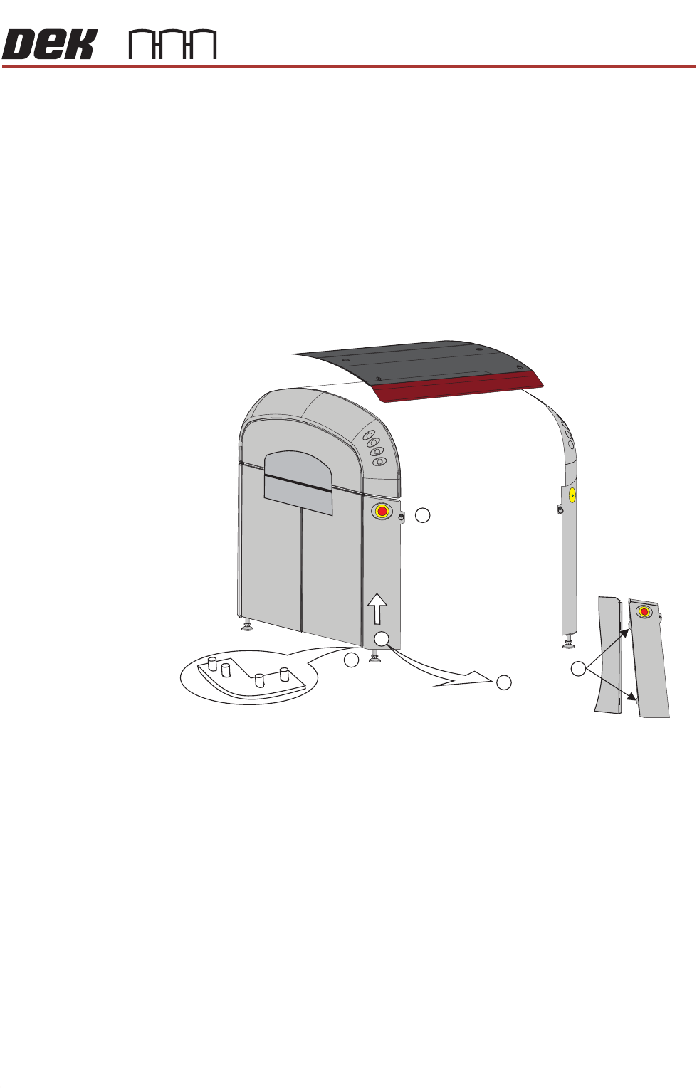
Corner Panels To remove a corner panel, carry out the following:
1. For the front corner panels, open the sliding cover; for the rear corner
panels, open the rear printhead cover.
2. Remove the respective Front/Rear Panel.
3. Locate and release the quarter-turn ring fastener that retains the corner
panel (1).
4. At the bottom of the corner panel, lift the panel up toward the upper side
panel (2), until it clears the locating pins at the base (3); tilt the panel out
away from the base plate (4).
5. Pull the corner panel away from the side panel to which it attached; all panels
are held together by interlocking panel locating tabs (5).
Front Left Quarter View
1
3
5
4
2
COVERS
PRINTER COVERS
2.20 Installation Manual Chapter Issue 12, Feb 18
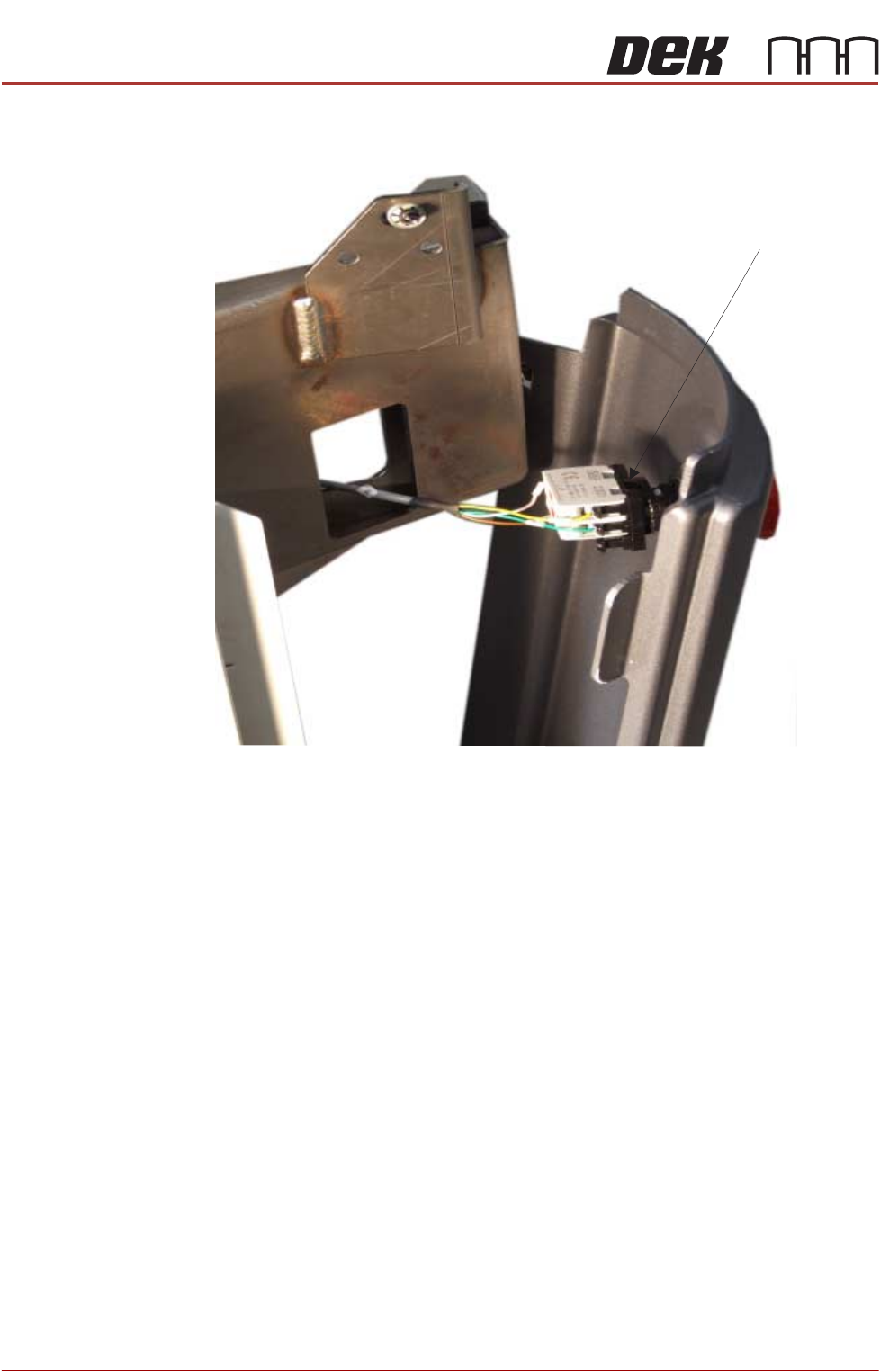
E Stop Switch
Removal
1. To complete the E Stop corner panel removal: turn the latch anti clockwise
to remove the contact assembly part of the E Stop switch.
2. Pull the contact away from the red mushroom switch. Remove the panel.
ESD Bonding Point To complete the removal of the ESD Bonding Point corner panel:
1. Remove the front panel, as previously described.
2. Locate the in-line filter and remove the spade connector.
3. Lift the panel away from bottom locating pins and separate the corner panel
away from the side panel tabs.
Latch