88192278-01-19 Installation Master.pdf - 第59页
COVERS PRINTER COVERS Chapter Issue 12, Feb 18 Installation Manual 2.25 2. T ilt the top of the panel away from the printe r and lift the panel clear , taking care not to damage the earth cable. Rear Covers T o remove th…
COVERS
PRINTER COVERS
2.24 Installation Manual Chapter Issue 12, Feb 18
Cover Removal Before removing covers ensure that the supplies (air and electrical) have been
isolated from the printer.
Front Panel To remove the front panel, carry out the following:
1. Open the front printhead cover.
2. Open the keyboard stowage door.
3. Disconnect the keyboard from the 4 port USB hub.
4. Remove the keyboard from its stowage.
5. Using a 4mm Allen key, undo the two captive screws on the rear side of the
panel.
6. Tilt the top of the panel away from the printer and lift the panel clear, taking
care not to damage the earth cable.
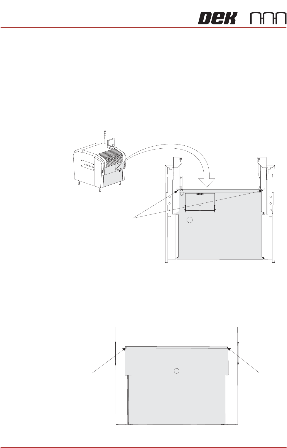
Rear Panel To remove the rear panel, carry out the following:
1. Using a 4mm Allen key, undo the two captive screws.
M5 Captive Screws
View on Rear of Front Panel
M5 Captive Screw
M5 Captive Screw
View on Rear of Machine
COVERS
PRINTER COVERS
Chapter Issue 12, Feb 18 Installation Manual 2.25
2. Tilt the top of the panel away from the printer and lift the panel clear, taking
care not to damage the earth cable.
Rear Covers To remove the rear fixed printhead cover, carry out the following:
1. Remove the rear panel (as detailed previously).
2. Using an 4mm Allen key, undo the two captive screws.
3. Remove the earth cable from the cover and lift the cover clear of the printer.
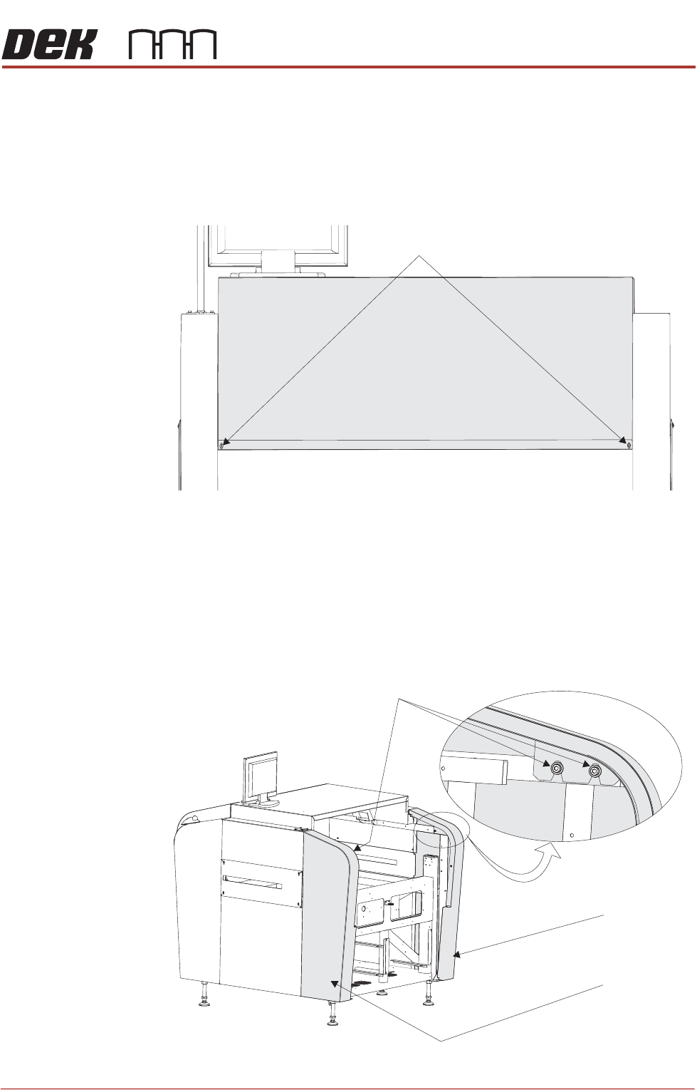
Rear Corner Panels To remove the rear corner panels, carry out the following:
1. Remove the rear panel (as detailed previously).
2. Remove the rear fixed printhead cover (as detailed previously).
3. Using an 4mm Allen key, undo the appropriate two captive screws.
4. Lift the panel clear of the printer, taking care not to damage the earth cable.
View on Rear of Machine
M5 Cap Screwstive
View on Rear - Right Quarter
M5 Cap Screwstive
Left Rear
Corner Panel
Right Rear
Corner Panel
COVERS
PRINTER COVERS
2.26 Installation Manual Chapter Issue 12, Feb 18
5. Repeat Steps 3 and 4 for the other rear corner panel, if required.
Front Corner Panels To remove the front corner panels, carry out the following:
1. Open the front printhead cover.
2. Remove the front panel (as detailed previously).
NOTE
1. Before a front corner panel can be removed, the control switches (jog
switch and system switch or jog switch and E Stop) must be disconnected.
2. Before removing the right hand front corner panel, disconnect the connec-
tor for the printhead safety switch.
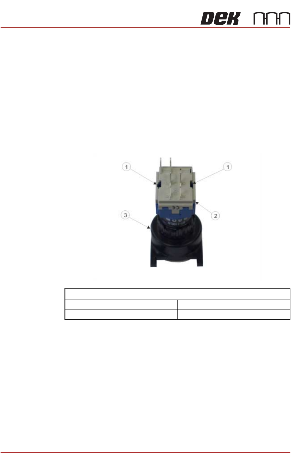
3. Locate the two release slots in the contact assembly part of the
switch.
View on Rear of Switch
1 Release Slot 3 Switch Body
2 Contact Assembly