88192278-01-19 Installation Master.pdf - 第65页
COVERS PRINTER COVERS Chapter Issue 12, Feb 18 Installation Manual 2.31 Cover Removal Before removing covers ensure that the supplie s (air and electrical) have been isolated from the printer . Earth Bonding All external…
COVERS
PRINTER COVERS
2.30 Installation Manual Chapter Issue 12, Feb 18
Type 4 Covers In order to protect personnel and prevent damage to the printer, eight panels
are fitted around the base of the printer.
• Front Panel
• Rear Panel
• Corner Panels (4 positions)
• Lower Side Panels (2 positions)
The upper part of the printer is protected by the front printhead cover, two front
corner panels, an MMI panel, a rear upper panel, the top rear panel and two
upper side panels.
NOTE
Some of the covers can only be removed in a specific order due to the covers
interlocking with each other.
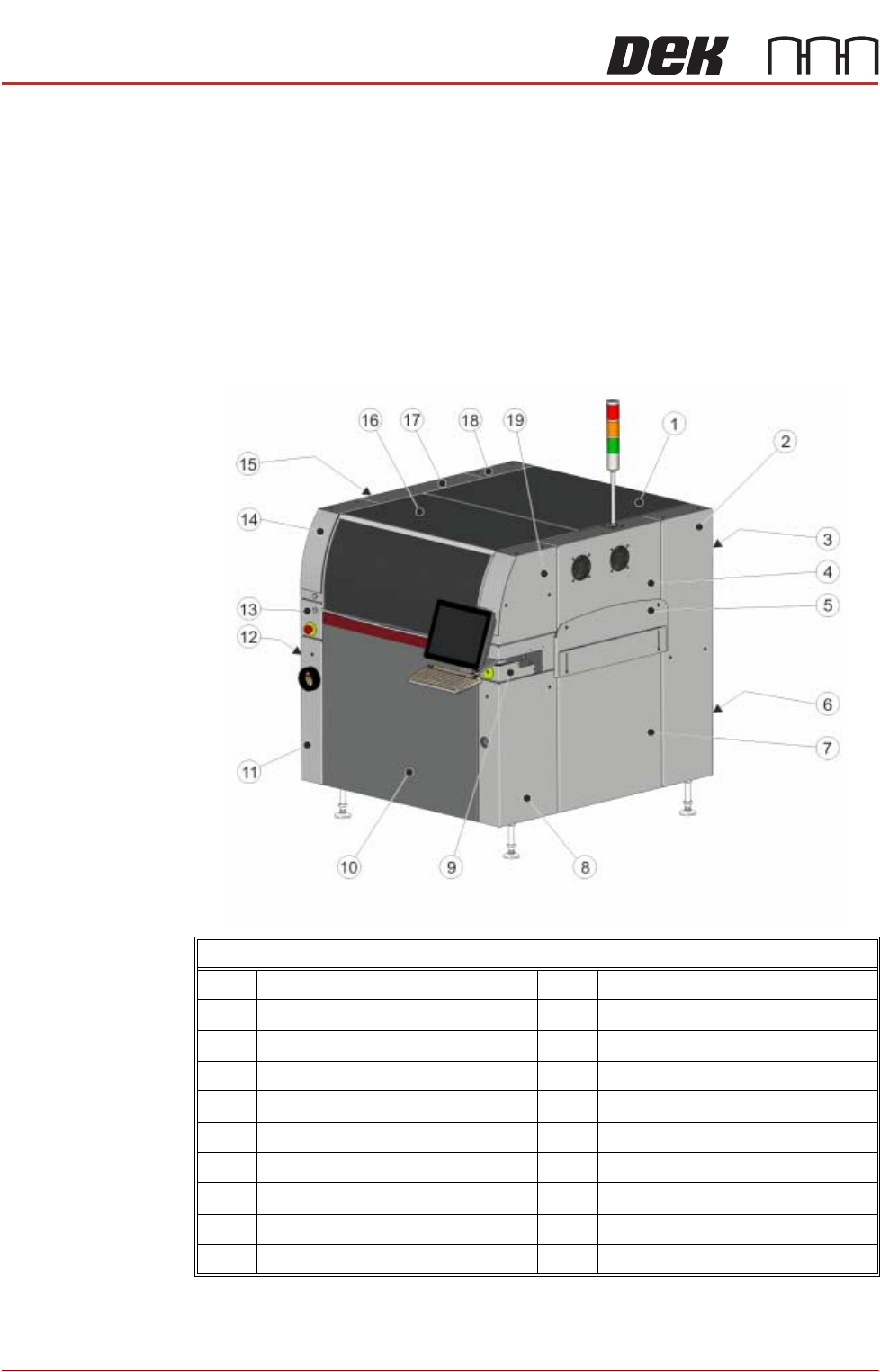
Front Right Quarter View
1 Top Rear Panel 11 Front Left Hand Lower Corner Panel
2 Rear Right Hand Corner Panel 12 Left Hand Lower Side Panel
3 Upper Rear Panel 13 Left Hand MMI Arm Panel
4 Right Hand Upper Side Panel 14 Front Left Hand Upper Corner Panel
5 Right Hand Safety Cover 15 Left Hand Safety Cover
6 Lower Rear Panel 16 Front Printhead Cover
7 Right Hand Lower Side Panel 17 Left Hand Upper Side Panel
8 Front Right Hand Lower Corner Panel 18 Rear Left Hand Corner Panel
9 Right Hand MMI Arm Panel 19 Front Right Hand Upper Corner Panel
10 Front Panel
COVERS
PRINTER COVERS
Chapter Issue 12, Feb 18 Installation Manual 2.31
Cover Removal Before removing covers ensure that the supplies (air and electrical) have been
isolated from the printer.
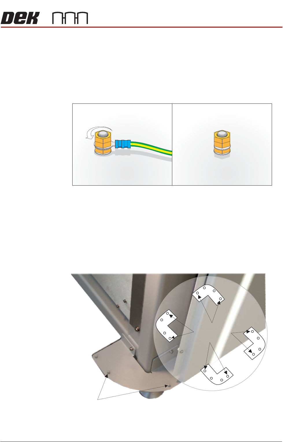
Earth Bonding All external metal surfaces are mechanically and electrically bonded to the
printer earth point. The bonding wire used is identified by its green and yellow
insulation and is commonly used to earth bond throughout.
Using an 8mm spanner, remove the two earth lead securing nuts and detach
the earth lead from the panel.
Care should be taken when removing these links, to ensure that when they are
replaced they are secured tightly and cleanly.
Locating Pins Side, corner, front and rear panels are secured on location pins at the base of
the printer. Plates mounted on each corner of the printer (see vignette below)
house the four pins; the two centre pins are for the corner panels and two outer
pins are for the side, front and rear panels.
Figure 2-9 Mounting Plates
Earth Stud
Corner Panel
Location Pins
View on Base of Printer
Location Pins
Side, Front &
Rear Panels
COVERS
PRINTER COVERS
2.32 Installation Manual Chapter Issue 12, Feb 18
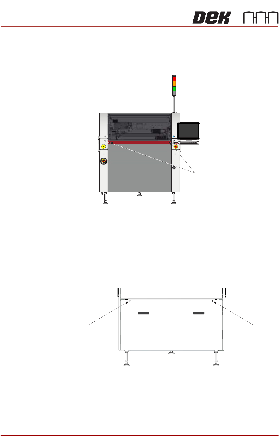
Front Panel To remove the front panel, carry out the following:
1. Open the front printhead cover.
2. Using a 4mm Allen key, undo the two captive screws on the front side of the
panel.
3. Tilt the top of the panel away from the printer and lift the panel clear of the
location pins that locate the panel to the printer frame, taking care not to
damage the earth cable.
Lower Rear Panel To remove the lower rear panel, carry out the following:
1. Using a 4mm Allen key, undo the two captive screws.
2. Tilt the top of the panel away from the printer and lift the panel clear of the
location pins that locate the panel to the printer frame, taking care not to
damage the earth cable.
M5 Captive Screws
View on Front of Machine
M5 Captive Screw
View on Rear of Machine
M5 Captive Screw