88192278-01-19 Installation Master.pdf - 第75页
COVERS PRINTER COVERS Chapter Issue 12, Feb 18 Installation Manual 2.41 9. Repeat Steps 1, 6, 7 and 8 fo r the other lower side panel, if required. Upper Side Panels T o remove the upper side panels, carry out the follow…
COVERS
PRINTER COVERS
2.40 Installation Manual Chapter Issue 12, Feb 18
6. Repeat Steps 3 to 4 for the other MMI Arm panel, if required. Full removal of
panel requires initial removal of the MMI Arm.
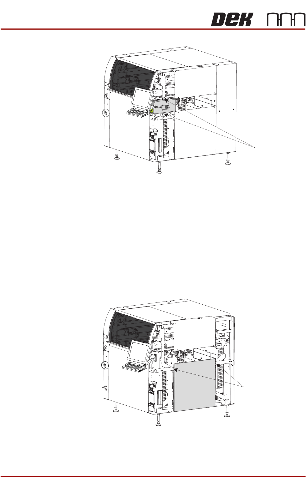
Lower Side Panels To remove the lower side panels, carry out the following:
1. Remove the corresponding safety cover (as detailed previously).
2. Open the front printhead cover.
3. Remove the front lower corner panels (as detailed previously).
4. Remove the front upper corner panels (as detailed previously).
5. Remove the rear corner panels (as detailed previously).
6. Remove the MMI Arm Panels (as detailed previously).
7. Using an 4mm Allen key, undo the two captive screws.
8. Tilt the top of the panel away from the printer and lift the panel clear, taking
care not to damage the earth cable.
Front Right Quarter View
Captive Screws
Front Right Quarter View
Captive Screws
COVERS
PRINTER COVERS
Chapter Issue 12, Feb 18 Installation Manual 2.41
9. Repeat Steps 1, 6, 7 and 8 for the other lower side panel, if required.
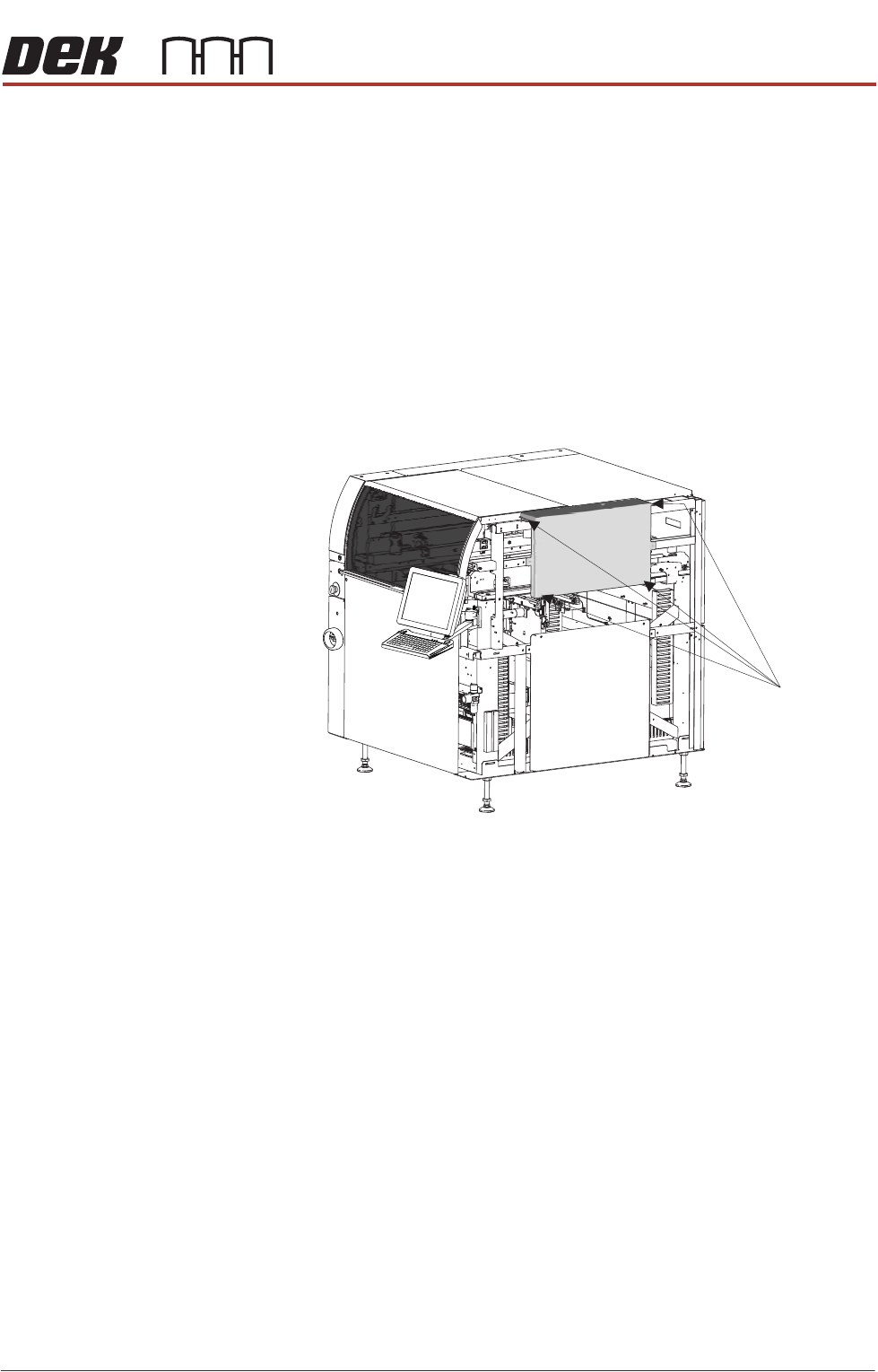
Upper Side Panels To remove the upper side panels, carry out the following:
1. Remove and disconnect the beacon.
2. Open the front printhead cover.
3. Remove the corresponding safety cover (as detailed previously).
4. Remove the upper front corner panel (as detailed previously).
5. Remove the lower front corner panel (as detailed previously).
6. Remove the MMI panel (as detailed previously).
7. Remove the corresponding rear corner panel (as detailed previously).
8. Remove the corresponding front corner panel (as detailed previously).
9. Using an 4mm Allen key, undo the four captive screws.
10.Lift the panel away from the printer, taking care not to damage the earth
cable.
11.Repeat Steps 3 to 9 for the other upper side panel, if required.
Front Right Quarter View
Captive Screws
(in 4 positions)
COVERS
PRINTER COVERS
2.42 Installation Manual Chapter Issue 12, Feb 18
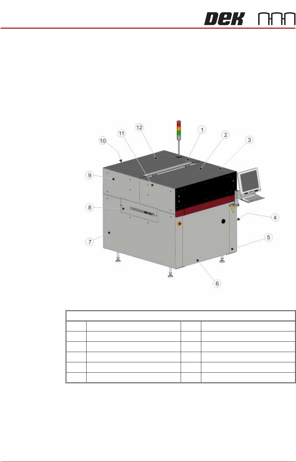
Type 5 Covers In order to protect personnel and prevent damage to the printer, four panels are
fitted around the base of the printer.
• Front Panel
• Rear Panel
• Lower Side Panels (2 positions)
The upper part of the printer is protected by the front printhead cover, two front
corner panels, two rear corner panels, and an upper panel rear.
NOTE
Some of the covers can only be removed in a specific order due to the covers
interlocking with each other.
Front Left Quarter View
1 Right Hand Upper Rear Corner Panel 7 Left Hand Side Cover
2 Front Printhead Cover 8 Left Hand Safety Cover
3 Right Hand Upper Front Corner Panel 9 Left Hand Upper Rear Corner Panel
4 Right Hand Safety Cover 10 Lower Rear Panel
5 Right Hand Side Cover 11 Left Hand Upper Front Corner Panel
6 Front Panel 12 Upper Rear Panel