YS24X_Mainte_E - 第102页
3-35 3 Periodic maintenance items 5 Oper ate the cleaning blow v alves. 1. Open the [Unit] - [I/O] screen. 2. Select "Head" from the Output drop- down list. Select the address of the head shaft blow (A table: T…
3-34
3
Periodic maintenance items
4.3 Operation check of head blow valve and cleaning blow valve
Check the operation of the head unit valve (solenoid valve). The head unit valve includes the following. One is
the blow valve that blows per head unit. The other one is the cleaning blow valve that blows strongly to clean
the inside of the shaft. If the valve does not work properly, it needs to be replaced. Replace it referring to
chapter 6, "3.2 Replacing a valve (solenoid valve)" and "3.3 Replacing the cleaning blow valve".
c
CAUTION
A strong air flow is exhausted during the cleaning blow. Always remove all nozzles attached to the heads before
starting the cleaning blow. Starting the cleaning blow while the nozzles are still attached may blow the nozzles away
from the heads causing the nozzles to break or become lost.
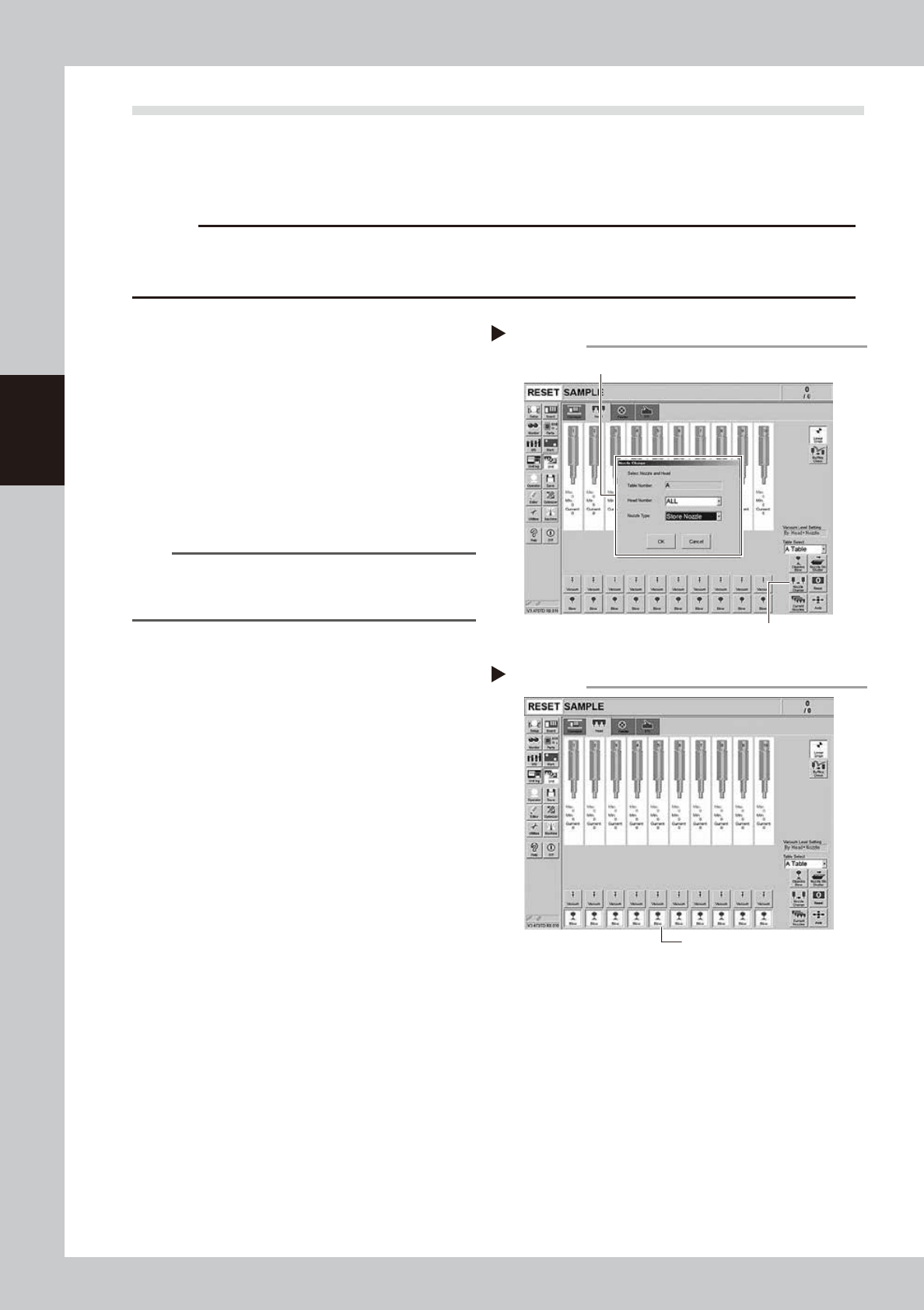
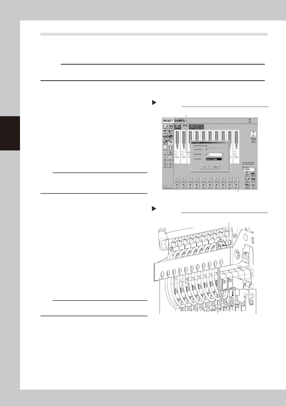
1
Remove the nozzles from all heads.
If nozzle station is equipped with the machine:
1. Press the [Nozzle Change] button on the
[Unit] - [Head] screen.
2. Select "ALL" for the Head Number and
select "Store Nozzle" for Nozzle type on
the "Nozzle Change" screen.
3. Press the [OK] button. The nozzles of all
heads are stored to the nozzle station.
54313-L4-00
n
NOTE
If the machine is not equipped with the nozzle station,
press the emergency stop button and then open the
machine safety cover to remove nozzles manually.
e
2
Move the head unit forward.
1. Press the emergency stop button and
then open the machine safety cover.
2. If the machine is equipped with a
carriage, remove the carriage to allow
you to easily access the head.
3. Move the head unit forward.
3
Blow each head.
Press all the [Blow] buttons on the [Unit] -
[Head] screen.
54306-L4-10
4
Check the blowing condition.
Place finger under each head. Check that
the air is exhausted equally from all heads. If
the less air is exhausted or the air is not
exhausted, a valve (solenoid valve) needs
to be replaced. Replace it referring to
chapter 6, "3.2 Replacing a valve (solenoid
valve)".
Storing nozzles
Step 1
Head Number : “ALL ”, Nozzle Type : “Store Nozzle”
[Nozzle Change] button
Blowing
[Blow] button
Step 2
3-35
3
Periodic maintenance items
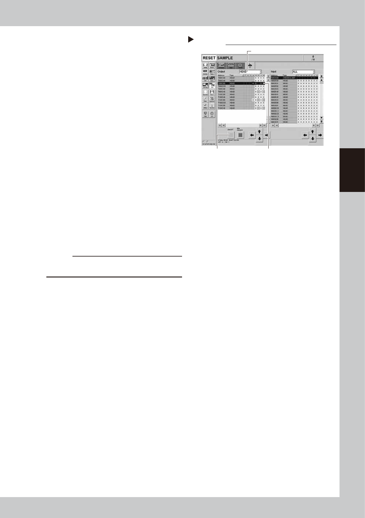
5
Operate the cleaning blow valves.
1. Open the [Unit] - [I/O] screen.
2. Select "Head" from the Output drop-
down list. Select the address of the head
shaft blow (A table: T002C804/B table:
T102C804).
3. Press the [ON/OFF] button on the left
once. The address indication changes
from 0 to 1. The cleaning blow valve start
operating.
54307-L4-10
6
Check the cleaning blow condition.
1. Place finger under each head. Check
that the stronger air is exhausted from all
heads.
2. Press the [ON/OFF] button on the [Unit]
- [I/O] screen again. The address
indication changes from 1 to 0. The
cleaning blow valve is closed.
3. Check that the less air is exhausted
If the strength of the air exhausted from the
head does not change even operating the
cleaning blow valve, the cleaning blow
valve needs to be replaced. Replace it
referring to chapter 6, "3.3 Replacing the
cleaning blow valve".
c
CAUTION
Make sure to wear safety goggles as the exhausted air
blow may strike face.
7
Shut the blow valve OFF.
Press the [Blow] buttons of all heads on the
[Unit] - [Head] screen to stop the blow
operation.
8
Return the nozzles.
Return the nozzles to the original position if
they were removed from the head manually.
Operating the cleaning blow valves.
Step 3
Press the [ON/OFF] button. Select an address.
Select a head.
3-36
3
Periodic maintenance items
4.4 Cleaning the inside of the spline shaft
Dust or grime may adhere to the air path of spline shafts and cause component pickup or mounting errors.
Although depending on the air supply condition and operating time, the inside of each spline shaft should be
cleaned once every 3 months.
c
CAUTION
If spline shaft movement becomes unstable or abnormal noise is emitted from a spline shaft, then contact YAMAHA
sales representative. Disassembly and cleaning of the spline shaft by the user will void the warranty.
4.4.1 Cleaning the inside of the spline shaft
1
Remove the nozzles from all heads.
With the nozzle station
1. Press the [Nozzle Change] button on the
[Unit] - [Head] screen.
2. Select "ALL" from the "Head Number" and
select "Store Nozzle" from the "Nozzle
Type" on the "Nozzle Change" screen.
3. Press the [OK] button to store all nozzles
in the nozzle station.
54314-L4-00
n
NOTE
If the machine is not equipped with a nozzle station,
remove all nozzles manually after opening the machine
safety cover
e
2
Move the head unit forward.
1. Press the emergency stop button and
then open the machine safety cover.
2. If the machine is equipped with a
carriage, remove the carriage to allow
you to easily access the head.
3. Move the head unit forward.
4. Place a square cloth under the head unit.
3
Disconnect the air hoses from each
spline shaft.
Remove the air hose of each head from the
joint. The joints are located on the ejector
side and the spline side respectively.
53334-L4-10
n
NOTE
It is not necessary to remove the air hose from the air
hose bracket.
Storing nozzles
Step 1
Head Number : “ALL ”, Nozzle Type : “Store Nozzle”
[Nozzle Change] button
Disconnecting the air hoses
Step 4
Joint (ejector side)
Joint (spline side)Air hose
Air hose bracket