YS24X_Mainte_E - 第106页
3-39 3 Periodic maintenance items 4.4.2 Checking the negative pressure After cleaning the spline shafts, chec k the negativ e pressure (vacuum lev el) generated in each head. 1 After assembly , check the vacuum lev els. …
3-38
3
Periodic maintenance items
7
Clean the inside of the spline shaft.
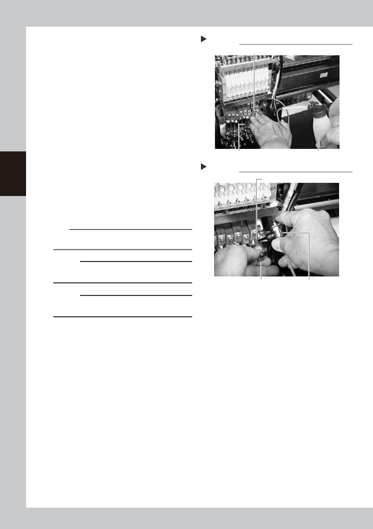
1. Insert the nozzle of the cleaning kit into
the cleaning hole of the spline shaft.
2. Pour IPA into the spline shaft air path to
clean away dust and grime.
53337-L4-00
8
Blow air into the spline air path.
1. Prepare an air blow tool (optional
purchase part) and connect it to a
nearby machine.
2. Place a cloth right under the head to be
cleaned.
3. Block the joint part with your finger to
avoid the air from leaking, and air blow
inside the spline shaft with the air blow
tool from the hole that the maintenance
bolt was removed.
4. Check that the dirt at the tip of the spline
shaft does not stick to a cloth.
5. Install the maintenance bolt.
53338-L4-10
n
NOTE
Repeat the Steps 8 to 9 until the IPA flowing from the
spline shaft is cleaned.
c
CAUTION
Make sure to wear safety goggles as the exhaust
blowing air might strike face.
c
CAUTION
A washer packing is fitted to the maintenance bolt. Be
careful not to drop it.
9
Repeat the steps 6 to 8.
Repeat the steps 6 to 8 to clean the inside
of spline shafts of all heads.
0
Reattach the air hose bracket to
its original position.
Secure the air hose bracket with the bolt
using the hex wrench.
q
Reconnect the air hoses back to
their original positions.
Return the nozzle to its original head if nozzle
was removed manually.
Cleaning the spline shaft
Step 7
Nozzle of cleaning kit
Spline shaft Pump of cleaning kit
Air blow into spline shaft
Step 8
Blow the air from this hole.
Air blow tool
Block the joint part with your finger.
3-39
3
Periodic maintenance items
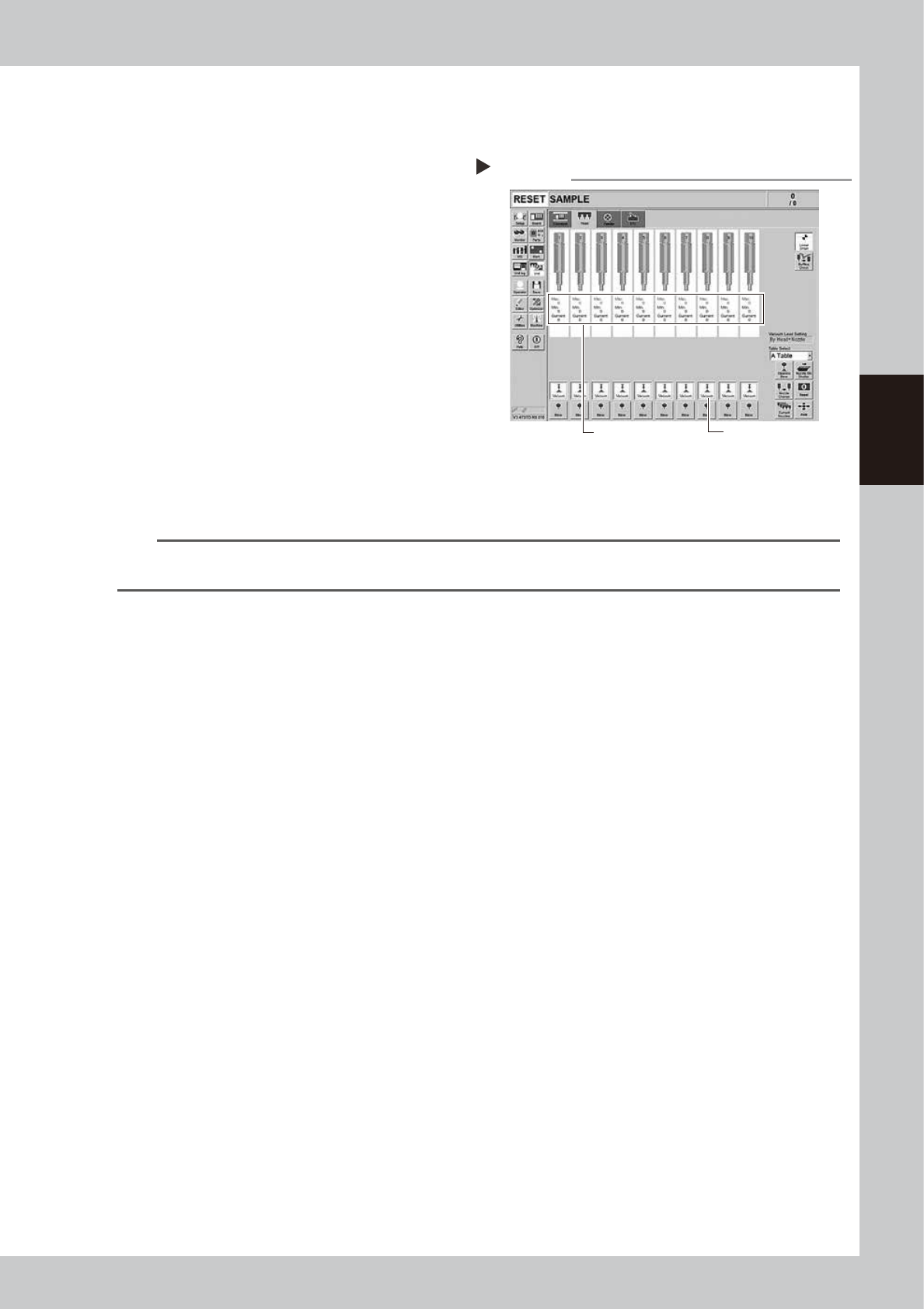
4.4.2 Checking the negative pressure
After cleaning the spline shafts, check the negative pressure (vacuum level) generated in each head.
1
After assembly, check the vacuum
levels.
1. Leave nozzles detached from the heads.
2. Press the [Vacuum] button in the [Unit]
– [Head] screen to generate a negative
pressure, and read the value displayed in
“Maximum Value” of the screen.
Check the value is the standard value or
less in the open state as shown below.
54309-L4-10
2
Reattach the nozzles.
Attach the nozzles by hand back to the
heads.
n
Vacuum level criteria in spline air path
No nozzles and open : 80 or less
When nozzle is sealed : 190 or more
n
NOTE
The vacuum level in the spline shaft air path might sometimes differ slightly depending on the air source and operating
conditions. Use the above criteria for reference during maintenance.
Checking the vacuum level
Step 1
[Vacuum] button
Read "Max" values.
3-40
3
Periodic maintenance items
4.5 Checking spline shaft operation
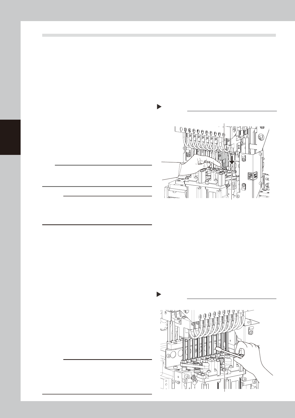
4.5.1 Checking spline shaft Z-axis operation
The following describes the operation inspecting of the spline shaft Z-axis.
e
1
Move the head unit.
1. Press the emergency stop button and then open the machine safety cover.
2. If the machine is equipped with a carriage, remove the carriage to allow you to easily access the
head.
3. Move the head unit forward.
2
Move spline shaft Z-axis up or
down.
Press down the lower part of the joint block
of the spline shaft Z-axis with finger. The joint
block returns to the original position by
releasing finger. Check that no heaviness,
unsteady movement, or abnormal sound
compare to the other spline shaft is found.
53364-L4-00
n
NOTE
If lacking grease on the surface of the spline shaft, the
surface may get rusted. Make sure not to touch the
shaft area.
c
CAUTION
If operating machine with the unsteady movement of
the spline shaft may cause fatal accidents. Stop
operating the machine if any abnormality is noticed
and contact YAMAHA sales representative.
4.5.2 Checking and cleaning around spline shaft
Check the area around the spline shaft.
e
1
Move the head unit.
1. Press the emergency stop button and then open the machine safety cover.
2. If the machine is equipped with a carriage, remove the carriage to allow you to easily access the
head.
3. Move the head unit forward.
2
Visually check around the spline
shaft.
Check that no dust or dirt is found on the
spline shaft.
3
Clean the spline shaft.
If dust or dirt is found on the spline shaft,
wipe it with a lint-free cloth or a cotton
swab.
53365-L4-00
c
CAUTION
If lacking grease on the surface of the spline shaft, the
surface may get rusted. Make sure not to wipe away
grease completely. However, if the grease is lacking
due to cleaning, apply anti-rust lubricant with the
procedure on the next.
Moving Z-axis
Step 2
Press down here with finger.
Joint block
Cleaning the spline shaft
Cotton swab
Step 3