YS24X_Mainte_E - 第110页
3-43 3 Periodic maintenance items 4 Clean the inside of the filter cup. 1. Lightly clean the filter cup with water . 2. Pour water-diluted neutral detergent into the filter cup and clean the inside. 3. After blowing air …
3-42
3
Periodic maintenance items
4.6 Inspecting and replacing the air and oil mist filter
The air filter and oil mist filter are used in this unit to prevent oil, water, impure objects in the air compressor
from entering into the machine. In this section, inspection and cleaning of these filters, and replacing method
of the inside filter element are shown below. In order to perform this work safely, always remove the air
coupler at the air supply connection unit.
1
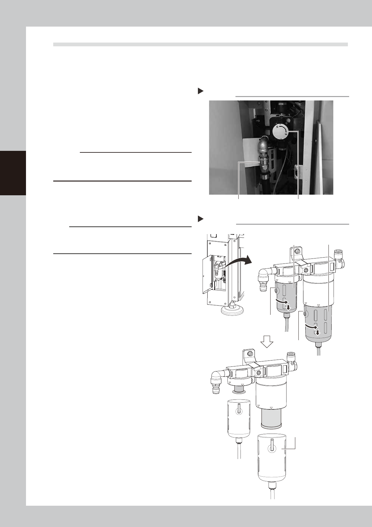
Remove the air coupler of air
supply.
1. Turn the air supply/exhaust switch
clockwise to turn air supply OFF.
2. Remove the air coupler on the air supply
connection unit.
53394-L4-10
c
CAUTION
Be aware that a loud air exhaust sound is heard when
disconnecting the air coupler. Use care to prevent oil,
water, and impurities, etc., from being sprayed out.
2
Check the inside of the filer cup.
Check if oil or water is in the cup. When oil
or water is dirty, clean it by following Step 3
to 4.
TIP
The drain valve at the bottom of cup is an auto-drain
type. When oil and water fills the cup, it is automatically
discharged.
3
Remove the cup.
1. While pressing the button on the filter
cup, turn the cup clockwise.
2. Match the button to the “IN” display
location on the filter housing, and pull
down the cup to remove.
53341-L4-10
Removing the filter cup
Step 3
Oil mist filter
Button
LOCK
IN
LOCK
IN
Button
Air filter
Filter cup
Step 1
Removing the air coupler
Air coupler Air supply/exhaust switch
3-43
3
Periodic maintenance items
4
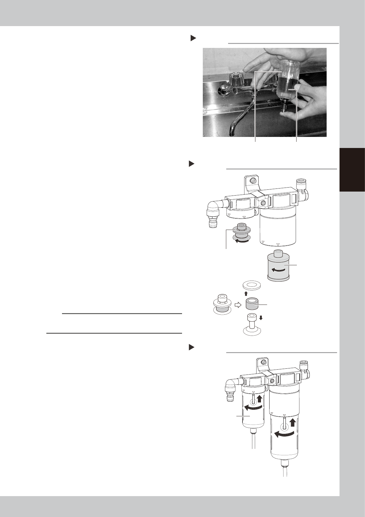
Clean the inside of the filter cup.
1. Lightly clean the filter cup with water.
2. Pour water-diluted neutral detergent into
the filter cup and clean the inside.
3. After blowing air to the filter cup, wipe
away any moisture with cloth.
53342-L4-00
5
Remove the filter element.
Air filter:
Turn the element ASSY counterclockwise
to remove.
The filter element is set between the top
and bottom adapters.
Oil mist filter:
Turn the filter element counterclockwise
to remove.
53367-L4-00
6
Check the state of element.
Check there is no dirt and clogging in the
filter element. If dirt and clogging are found,
replace with a new filter element.
7
Attach the filter element.
Follow the reverse order of removing the
element to remove the filter element.
8
Attach the cup.
1. Match the cup’s button to the displayed
location of “IN” on the filter housing, and
push the cup up.
2. Turn the cup counterclockwise to the
displayed location of “LOCK”.
53395-L4-00
TIP
You hear a click sound when the cut is set on the
“LOCK” location properly.
9
Reconnect the air coupler.
1. After reconnecting the air coupler, check
that no air is leaking.
2. Turn the air supply/exhaust switch
counterclockwise to restart air supply.
Cleaning the filter cup
Step 4
Filter cup
Water-diluted
neutral detergent
Removing the filter element
Step 5
Mist filter element
(Air) filter element
Filter element ASSY
Lock
IN
Lock
IN
Reattaching the filter cup
Step 8
Filter cup
3-44
3
Periodic maintenance items
4.7 Dual stage only: Cleaning and lubrication of U axis (W2 axis)
In case the specification is the dual stage machine, cleaning and lubrication of the ball screw of U axis (W2
axis), guide, and hex spline approx. every three months. For lubrication places, refer to "Chapter 5 Lubrication
points and schedule" also.
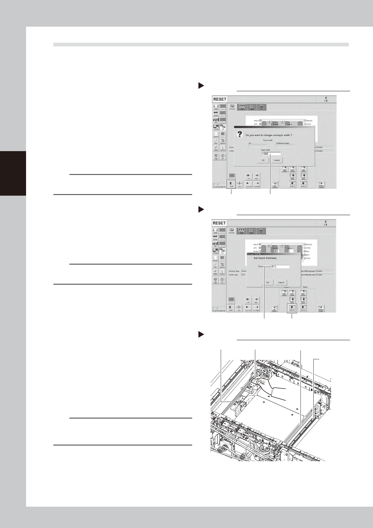
1
Change the conveyor width to its
maximum width.
1. Press the [Conveyor Width] button on the
[Unit] – [Conveyor] screen to display the
“Conveyor Width” screen.
2. Enter the maximum value of the
conveyor width in the “Changed
conveyor width”, press [OK]. The
conveyor is changed to the width that
was just entered.
54315-L4-00
TIP
The maximum value of the conveyor width is 460 mm as
the standard specification.
2
Move the stage 2 up.
1. Push the [Stage 2] - [Pushup] button to
display the “Conveyor Pushup” screen.
2. Enter “0.1 mm” in Thickness, and press
the [OK] button. The stage 2 moves up.
54316-L4-00
n
NOTE
By moving up the stage 2, it becomes easier to access
the ball screw and guide.
e
3
Clean each part of U-axis (W2 axis).
1. Press the emergency stop button, and
open the machine’s safety cover.
2. If the machine is equipped with a
carriage, remove to the carriage for
easy access to the U-axis.
3. Remove everything affected by
magnetism such as wrist watches,
magnetic ID card, etc.
4. Clean the old grease and dirt of the
whole U axis ball screw (2), guide (2),
and hex spline (1) with a lint-free cloth
that does not raise dust.
53334-L4-10
n
NOTE
When performing cleaning, clean the lead groove part
of the ball screw and the groove of the guide rail
carefully. Also, make sure no dust is generated.
Changing the conveyor width
Step 1
[width] button Enter the maximum conveyor value
Enter the pushup board thickness
Step 2
[Push Up] buttonEnter the thickness
Cleaning the each part of U-axis
Step 3
Guide
Lint-free clothHexagon spline
Ball screw