YS24X_Mainte_E - 第126页
Chapter 5 Lubrication points and schedule Contents 1. Lubrication preparations 5-1 1.1 Compatible grease 5-1 1.2 Grease gun 5-1 2. Lubrication points and schedule (Main machine) 5-2 2.1 X-axis 5-2 2.2 Y -axis 5-3 2.3 W-a…
4-6
4
Maintenance of options
5
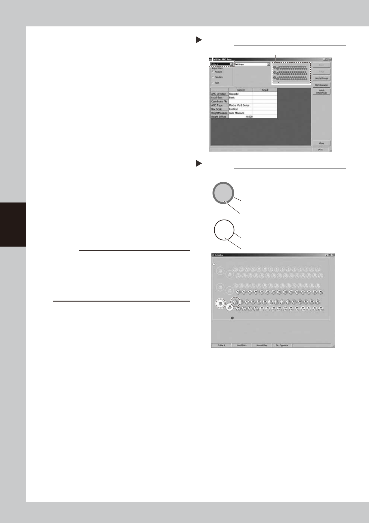
Open the ANC Auto screen.
Press the [024 ANC Auto] button.
1. Select a desired table from the pull-down
menu at the upper left portion of the
screen.
2. Click the ANC illustration on the right.
54404-L4-00
6
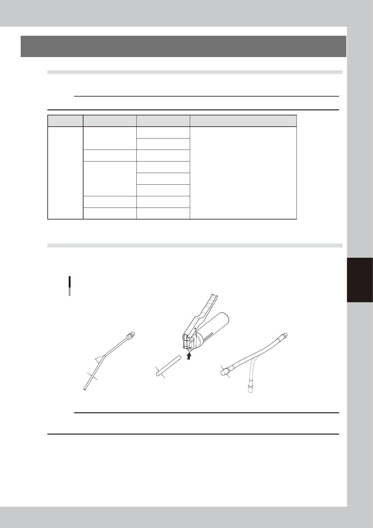
Check the ANC sensor operation.
1. Check that the nozzle storage status
shown on the screen is the same as the
actual nozzle storage status while
referring to the nozzle storage position/
sensor status in the illustration.
2. Remove the nozzle by hand and check
that no nozzle is displayed at the target
storage position.
54405-L4-00
7
Clean the ANC.
If the nozzle detection status is different from
the actual nozzle presence status, remove
the nozzle and visually check the inside. If
any dust or chip is found, remove it and
clean the inside of the nozzle using the
vacuum assembly.
c
CAUTION
If the nozzle detection status inside the ANC does not
become stable for a reason other than clear reason,
such as dust, etc., or if the nozzle cannot be detected,
contact YAMAHA sales representative. The disassembly
and cleaning performed by the customer are not
covered by the warranty.
8
Close the ANC shutter.
Press the [Nozzle Stn Shutter] button to close
the ANC shutter.
Opening the ANC Auto screen
Step 5
Select the table A or table B. Click the ANC illustration.
2-303
79
3-SP
80
Checking the ANC sensor operation
Step 6
303 nozzle to be used for head 2
Storage position: No. 79
Colored frame (red/blue/yellow/green, etc.):
Nozzle is already registered.
Special nozzle to be used for head 3
Storage position: No. 80
Black frame: Nozzle is not registered.
Gray out: Nozzle is present currently.
White: Nozzle is not present currently.
Example of nozzle storage position/sensor status

Chapter 5 Lubrication points and schedule
Contents
1. Lubrication preparations 5-1
1.1 Compatible grease 5-1
1.2 Grease gun 5-1
2.
Lubrication points and schedule (Main machine)
5-2
2.1 X-axis 5-2
2.2 Y-axis 5-3
2.3 W-axis (U-axis) 5-4
2.3.1 Dual-stage specifications 5-4
2.3.2 Dual-lane and single-lane specifications 5-5
2.3.3 Single-lane specifications 5-6
2.4 PU-axis 5-7
2.4.1 Dual-stage specifications 5-7
2.4.2 Dual-lane specifications 5-7
2.4.3. Single-lane specifications 5-8
2.5 Z-axis (Spline shaft) 5-9
5-1
5
Lubrication points and schedule
1. Lubrication preparations
1.1 Compatible grease
For greasing procedures, always use the YAMAHA prescribed grease shown below.
c
CAUTION
Using unauthorized grease could damage the machine.
Lube Point Guide Grease
Main unit
X-axis
Ball screw
NSL grease
Part No. : K48-M3856-00X
Guide
Y-axis Ball screw
W-axis (U-axis)
Ball screw
Guide
Hexagon spline
PU-axis Ball screw
Head Z-axis Spline shaft
1.2 Grease gun
The grease gun has 3 interchangeable nozzle types to accommodate the various greasing point configurations.
Always use the prescribed nozzle for the greasing point in question.
Grease gun
Grease gun
30° bend type nozzle
Standard nozzle
The various
nozzle tips are
inserted here
Flexible chuck type nozzle
30°
OD ø14 tip
OD ø10 tip
OD ø0.5 tip
53500-L4-00
c
CAUTION
Prepare the tip nozzle for grease to be used. If two or more kinds of grease with different characteristics are mixed in
the nozzle and it is applied, this may cause the machine performance to lower.