YS24X_Mainte_E - 第155页
Appendix Appendix Contents 1. Specifications A-1 1.1 Air regulator unit A-1 1.2 Power connection terminals A-2 1.3 Connection between machines A-3 1.3.1 PREVIOUS INTERF ACE connector A-3 1.3.2 NEXT INTERF ACE connector A…
6-18
6
How to replace consumable parts
r
Check the belt rotating condition.
1. Make sure that the board clamp top
surface is approx. 0.5mm lower than the
belt upper surface.
2. Close the machine’s safety cover, and
cancel the emergency stop. If the
machine could be equipped with a
carriage, set the carriage.
3. On the [Unit] - [Conveyor] screen, press
the [Conveyor In] button or [Conveyor
Out] button to turn on the conveyor
motor and check the belt rotation.
4. If the rotation speed fluctuates or there is
slack in the belt, adjust the position of
the pulley that tension is applied, and
adjust the pulley’s position again.
54603-L4-00
c
CAUTION
When the difference between the belt upper surface
and board clamp top surface is very little, the board
transfer error may occur easily. In this case, contact
YAMAHA sales representative.
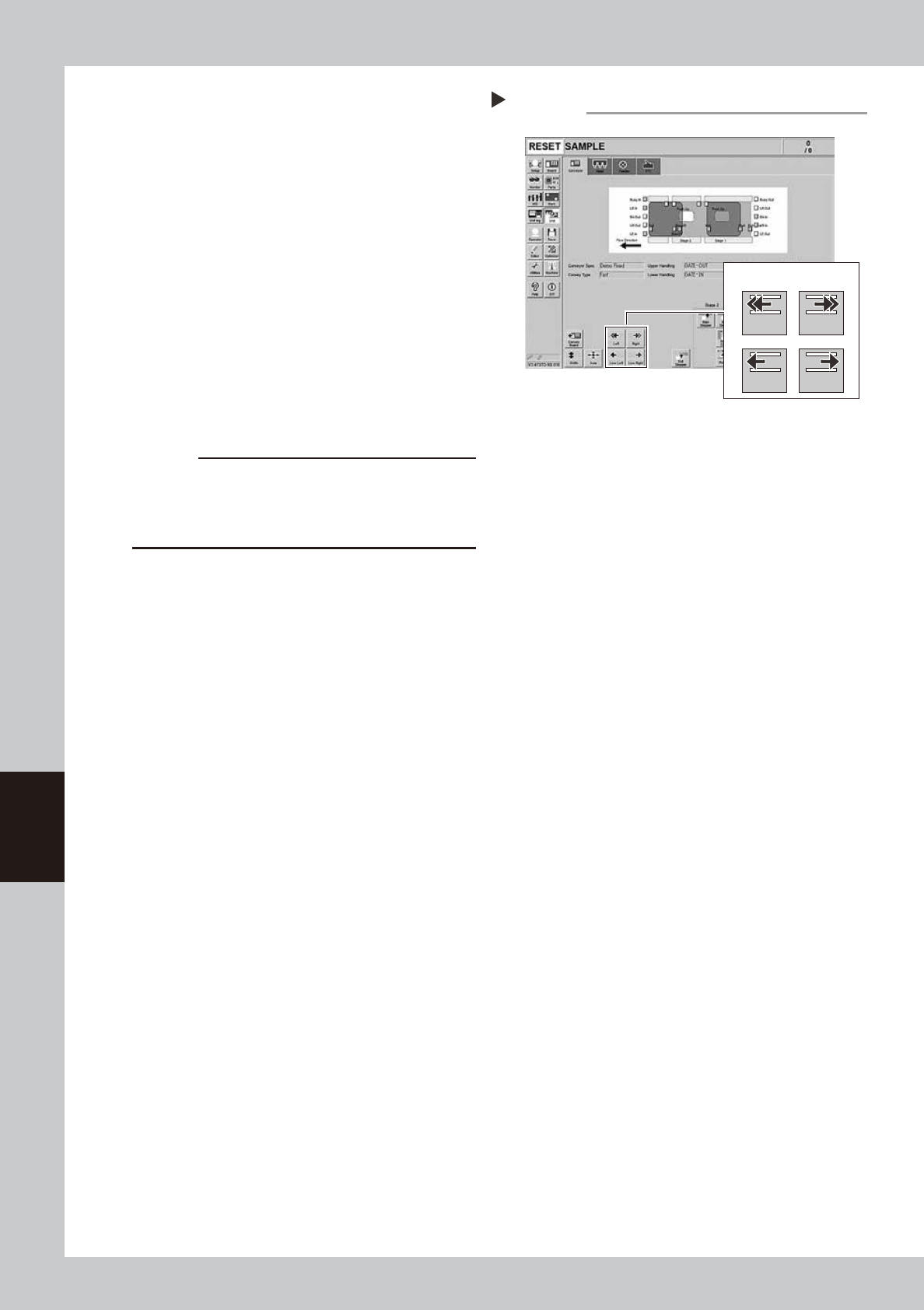
Conveyor operation check
Step 14
Conveyor drive buttons
Left Right
Low Left Low Right

A-1
Appendix
1. Specifications
1.1 Air regulator unit
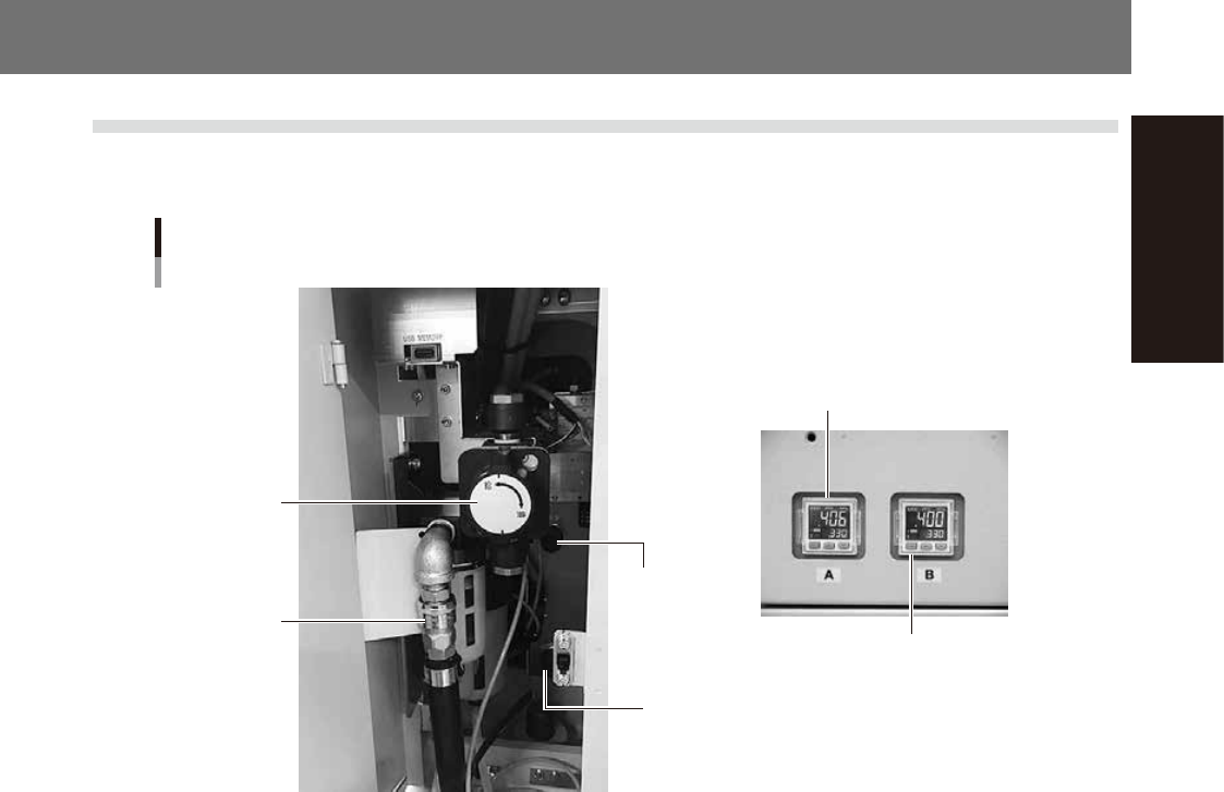
The air regulator for controlling the air pressure to the pneumatic units of the machine is located behind the
front lower left panel. A digital pressure gauge is provided on the front left of the machine.
Air pressure regulator and pressure gauge
Digital pressure gauge (A-table)
Digital pressure gauge (B-table)
Source air
connector
Air pressure
regulator
(B-table)
Air pressure
regulator
(A-table)
Air supply/exhaust
switch (valve)
53A01-L4-10
n
Supply air pressure
This is the pressure of the source air supplied to the machine. Before setting the air pressure with the air regulator, make
sure that this supply air pressure is in the following optimal range.
YS24X : 0.45MPa to 0.70MPa
n
Digital pressure gauge
Shows the supply air pressure (upper reading) and pressure-drop detection level (lower reading). A normal pressure value
is shown in green, and a pressure value lower than the pressure-drop detection level is shown in red.
n
Air pressure setting and pressure-drop detection level
Air pressure setting for machine (upper reading) : 0.40MPa to 0.41MPa
Pressure-drop detection level (lower reading) : 0.33MPa
n
Air supply/exhaust switch (valve)
Turning this switch to the right shuts off air supply and exhausts air that remains inside the machine.
n
Source air connector
Prepare an air hose with an inner diameter of at least 8mm having a 40SH socket (Nitto Koki, or equivalent), and connect
it to this connector. Use dry, clean air passed through an air filter.