YS24X_Mainte_E - 第157页
A-2 Appendix 1.2 Power connection terminals T he power connection terminals are located inside the lower right panel on the front of the machine. Connect the power cable leads as shown belo w to the L1, L2, L3 and ground…
A-1
Appendix
1. Specifications
1.1 Air regulator unit
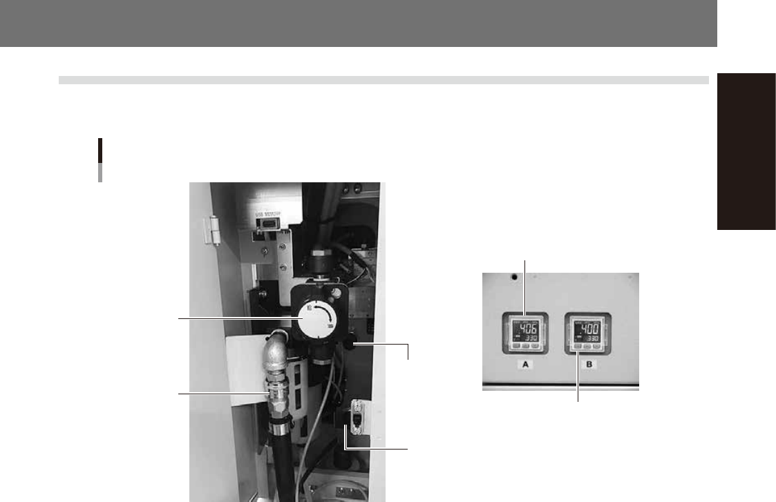
The air regulator for controlling the air pressure to the pneumatic units of the machine is located behind the
front lower left panel. A digital pressure gauge is provided on the front left of the machine.
Air pressure regulator and pressure gauge
Digital pressure gauge (A-table)
Digital pressure gauge (B-table)
Source air
connector
Air pressure
regulator
(B-table)
Air pressure
regulator
(A-table)
Air supply/exhaust
switch (valve)
53A01-L4-10
n
Supply air pressure
This is the pressure of the source air supplied to the machine. Before setting the air pressure with the air regulator, make
sure that this supply air pressure is in the following optimal range.
YS24X : 0.45MPa to 0.70MPa
n
Digital pressure gauge
Shows the supply air pressure (upper reading) and pressure-drop detection level (lower reading). A normal pressure value
is shown in green, and a pressure value lower than the pressure-drop detection level is shown in red.
n
Air pressure setting and pressure-drop detection level
Air pressure setting for machine (upper reading) : 0.40MPa to 0.41MPa
Pressure-drop detection level (lower reading) : 0.33MPa
n
Air supply/exhaust switch (valve)
Turning this switch to the right shuts off air supply and exhausts air that remains inside the machine.
n
Source air connector
Prepare an air hose with an inner diameter of at least 8mm having a 40SH socket (Nitto Koki, or equivalent), and connect
it to this connector. Use dry, clean air passed through an air filter.
A-2
Appendix
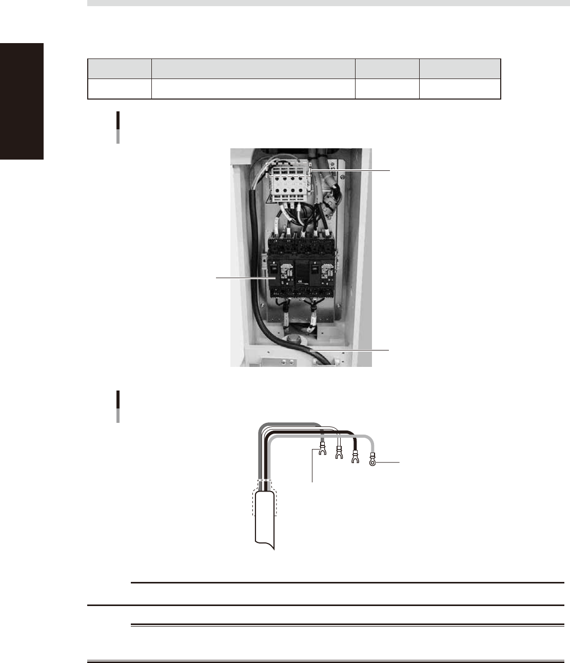
1.2 Power connection terminals
The power connection terminals are located inside the lower right panel on the front of the machine. Connect
the power cable leads as shown below to the L1, L2, L3 and ground terminal (PE) on the power terminal block.
n
Power supply specifications
Model name Power Frequency Power capacity
YS24X 3-phase AC 200/208/220/240/380/400/416V (±10%) 50/60Hz 7.7kVA
Power input terminals
(L1, L2, L3) and ground terminal
Main breaker
Power cable
Power connection terminals
53A02-L4-00
Fork-tongue crimp terminal
Power cable example
L1
L2
L3
PE
L=100mm
Ring-tongue crimp terminal
53A05-L4-00
c
CAUTION
Use a power cable whose conductor cross-section area is greater than 5.5mm
2
.
w
WARNING
TO AVOID THE RISK OF ELECTRICAL SHOCK, MAKE SURE THAT THE POWER SOURCE IS OFF BEFORE CONNECTING THE
POWER CABLE. ALSO MAKE SURE THAT THE GROUND CABLE IS SECURELY CONNECTED TO THE MACHINE.
A-3
Appendix
1.3 Connection between machines
To exchange signals such as board request and operation status with the downstream or upstream machine, the
"NEXT INTERFACE" and "PREVIOUS INTERFACE" connectors located on the rear of the machine are used. The
"NEXT INTERFACE" connector connects to the downstream machine, and the "PREVIOUS INTERFACE"
connector connects to the upstream machine such as a loader. In the case of standard right-to-left flow, the
PREVIOUS INTERFACE connector is located inside the lower right cover on the rear of the machine while the
NEXT INTERFACE connector is located inside the lower left cover on the rear of the machine.
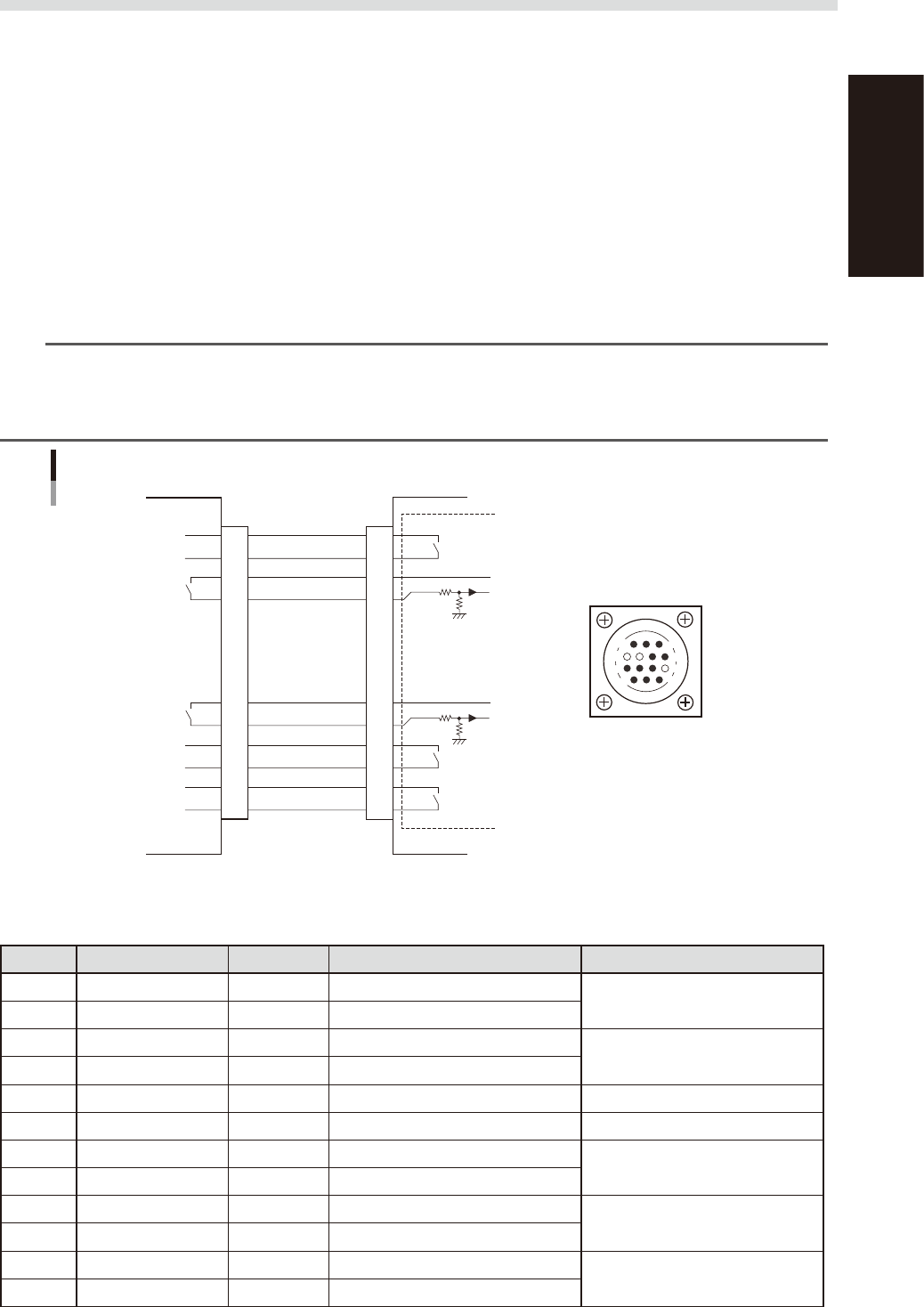
1.3.1 PREVIOUS INTERFACE connector
When the following three conditions are met, the PREVIOUS INTERFACE circuit in the machine allows the
next board to be carried in. (ADVANCED GATE is selected.)
1. Machine is ready for carrying in a board (BUSY OUT: ON)
2. Board carry-in signal is input from the upstream machine. (BA IN [N0100421] : ON)
3. Automatic operation signal is input from the upstream machine. (UR IN [N0100422] : ON)
n
NOTE
• When the automatic operation signal (UR IN) from the loader turns off during transfer of a board, the machine
temporarily stops carrying in the board.
• When the board being carried in is detected by the entrance sensor, the BUSY OUT signal turns off.
• Carrying in the board is finished when both the BUSY OUT and BA IN turn off.
1
2
3
4
5
6
7
8
9
10
11
12
13
14
7
12
4
8
1
14
11
3
BUSY OUT
(T01000E4)
+24V
+24V
LR OUT
(T01000E7)
UR IN
(N0100422)
BA IN
(N0100421)
Signal input during
board carry-in
Signal output to
request board carry-out
Signal output during
automatic operation
Signal input during
automatic operation
LE OUT
(T01000F3)
Signal input during
waiting for board
between machines
I/O BOARD
PREVIOUS INTERFACE circuit
This machine PREVIOUS INTERFACEUpstream
PREVIOUS INTERFACE
connector
AMP 206043-1
(14-pin receptacle)
53A03-L4-00
n
Board transfer signal specifications
PREVIOUS INTERFACE
Pin No. Signal name Address I/O specifications Signal specifications
1 BUSY OUT T01000E4 Relay contact (zero voltage) output
Signal output during board carry-in
2 BUSY OUT T01000E4 Relay contact (zero voltage) output
3 +24V Input common (+24V)
Signal input of board carry-out
request
4 BA IN N0100421 Voltage input
5 NC (with dummy pins) (Prevents misinsertion.)
6 to 8 NC
9 +24V Input common (+24V)
Signal input during automatic
operation
10 UR IN N0100422 Voltage input
11 LR OUT T01000E7 Relay contact (zero voltage) output
Signal output during automatic
operation
12 LR OUT T01000E7 Relay contact (zero voltage) output
13 LE OUT T01000F3 No-voltage output
Signal output during waiting for
board between machines
14 LE OUT T01000F3 No-voltage output