YS24X_Mainte_E - 第159页
A-4 Appendix 1.3.2 NEXT INTERF ACE connector When the following three conditions are met, the NEXT INTERF A CE circuit in the machine allo ws the board to be carried out. 1. Machine is read y for carrying out the board (…
A-3
Appendix
1.3 Connection between machines
To exchange signals such as board request and operation status with the downstream or upstream machine, the
"NEXT INTERFACE" and "PREVIOUS INTERFACE" connectors located on the rear of the machine are used. The
"NEXT INTERFACE" connector connects to the downstream machine, and the "PREVIOUS INTERFACE"
connector connects to the upstream machine such as a loader. In the case of standard right-to-left flow, the
PREVIOUS INTERFACE connector is located inside the lower right cover on the rear of the machine while the
NEXT INTERFACE connector is located inside the lower left cover on the rear of the machine.
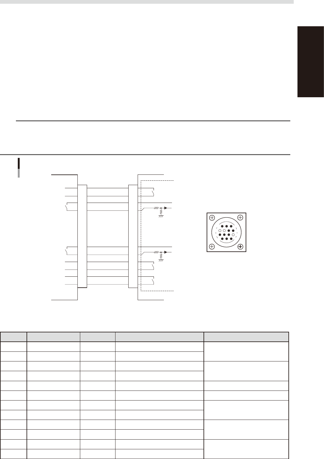
1.3.1 PREVIOUS INTERFACE connector
When the following three conditions are met, the PREVIOUS INTERFACE circuit in the machine allows the
next board to be carried in. (ADVANCED GATE is selected.)
1. Machine is ready for carrying in a board (BUSY OUT: ON)
2. Board carry-in signal is input from the upstream machine. (BA IN [N0100421] : ON)
3. Automatic operation signal is input from the upstream machine. (UR IN [N0100422] : ON)
n
NOTE
• When the automatic operation signal (UR IN) from the loader turns off during transfer of a board, the machine
temporarily stops carrying in the board.
• When the board being carried in is detected by the entrance sensor, the BUSY OUT signal turns off.
• Carrying in the board is finished when both the BUSY OUT and BA IN turn off.
1
2
3
4
5
6
7
8
9
10
11
12
13
14
7
12
4
8
1
14
11
3
BUSY OUT
(T01000E4)
+24V
+24V
LR OUT
(T01000E7)
UR IN
(N0100422)
BA IN
(N0100421)
Signal input during
board carry-in
Signal output to
request board carry-out
Signal output during
automatic operation
Signal input during
automatic operation
LE OUT
(T01000F3)
Signal input during
waiting for board
between machines
I/O BOARD
PREVIOUS INTERFACE circuit
This machine PREVIOUS INTERFACEUpstream
PREVIOUS INTERFACE
connector
AMP 206043-1
(14-pin receptacle)
53A03-L4-00
n
Board transfer signal specifications
PREVIOUS INTERFACE
Pin No. Signal name Address I/O specifications Signal specifications
1 BUSY OUT T01000E4 Relay contact (zero voltage) output
Signal output during board carry-in
2 BUSY OUT T01000E4 Relay contact (zero voltage) output
3 +24V Input common (+24V)
Signal input of board carry-out
request
4 BA IN N0100421 Voltage input
5 NC (with dummy pins) (Prevents misinsertion.)
6 to 8 NC
9 +24V Input common (+24V)
Signal input during automatic
operation
10 UR IN N0100422 Voltage input
11 LR OUT T01000E7 Relay contact (zero voltage) output
Signal output during automatic
operation
12 LR OUT T01000E7 Relay contact (zero voltage) output
13 LE OUT T01000F3 No-voltage output
Signal output during waiting for
board between machines
14 LE OUT T01000F3 No-voltage output
A-4
Appendix
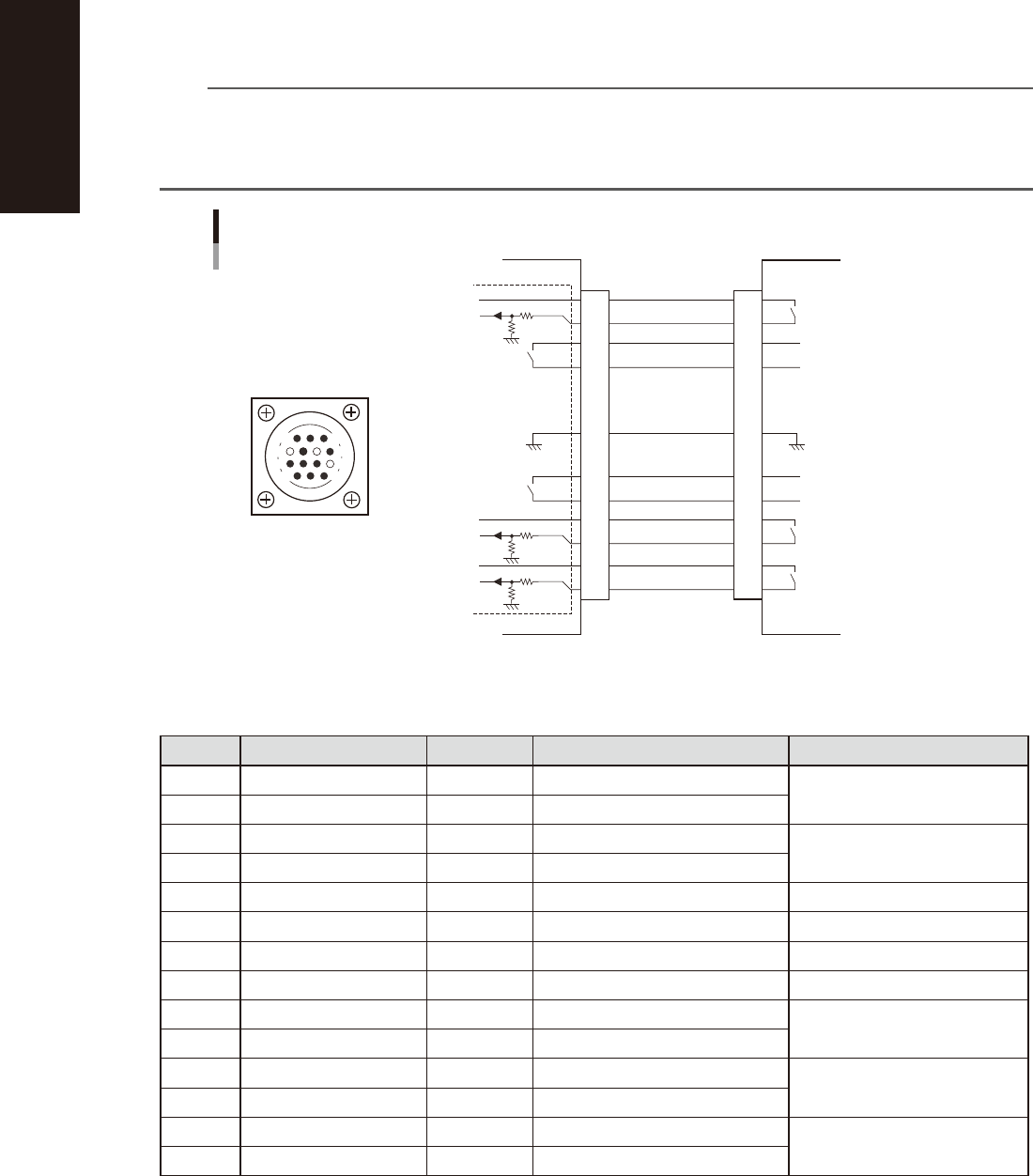
1.3.2 NEXT INTERFACE connector
When the following three conditions are met, the NEXT INTERFACE circuit in the machine allows the board to
be carried out.
1. Machine is ready for carrying out the board (BA OUT: ON)
2. Board carry-in signal is input from the downstream machine. (BUSY IN [N0100420] : ON)
3. Automatic operation signal is input from the downstream machine. (LR IN [N0100423] : ON)
n
NOTE
• When the automatic operation signal (LR IN) from the downstream machine turns off during transfer of a board,
the machine stops temporarily carrying out the PC.
• When the board being carried out is detected by the exit sensor, the BA OUT signal turns off.
• Carrying out the board is finished when both the BUSY IN and BA OUT turn off.
1
2
3
4
5
6
7
8
9
10
11
12
13
14
BUSY IN
(N0100420)
+24V
+24V
UR OUT(T01000E6)
LR IN
(N0100423)
+24V
LE IM
(N0100424)
BA OUT
(T01000E5)
Signal output during waiting
for board between machines
I/O BOARD
GND GND
14
11
12
7
4
8
3
1
Signal output during board
carry-in
Signal input to request board
carry-out
NEXT INTERFACE circuit
NEXT INTERFACE
connector
NEXT INTERFACE
AMP 206043-1
(14-pin receptacle)
This machine
Downstream machine
Signal input during automatic
operation
Signal output during automatic
operation
53A04-L4-00
n
Board transfer signal specifications
NEXT INTERFACE
Pin No. Signal name Address I/O specifications Signal specifications
1 +24V Input common (+24V)
Signal input during board carry-in
2 BUSY IN N0100420 Voltage input
3 BA OUT T01000E5 Relay contact (zero voltage) output
Signal output to request board
carry-out
4 BA OUT T01000E5 Relay contact (zero voltage) output
5 NC
6 NC (with dummy pins) (Prevents misinsertion.)
7 GND
8 NC
9 UR OUT T01000E6 Relay contact (zero voltage) output
Signal output during automatic
operation
10 UR OUT T01000E6 Relay contact (zero voltage) output
11 +24V Input common (+24V)
Signal input during automatic
operation
12 LR IN N0100423 Voltage input
13 +24V Input common (+24V)
Signal input during waiting for
board between machines
14 LE IN N0100424 Voltage input

A-5
Appendix
2. Warranty
The machine you have purchased is warranted against malfunctions as described below.
n
Warranty description:
If a failure or breakdown occurs due to defects in workmanship or materials used to manufacture this machine within
one year or 5,000 hours of operation (whichever comes first) after the incoming inspection is complete, then YAMAHA
will repair the defective parts free of charge.
n
Warranty period
The warranty period ends when any of the following applies:
1. After one year has elapsed from the time of installation.
2. After 5,000 hours of operation.
n
Items not covered by the warranty
The warranty does not cover any of the following conditions:
1. Damage as a result of deterioration due to age or wear (e.g., normal discoloration of painted or plated surfaces, wear
of replaceable parts, etc.).
2. Incidents associated with sensory perceptions which have no bearing on the quality or function of the machine (e.g.,
signal sounds emitted by the controller, rotating sounds of the motor, etc.).
3. Damage caused by the user environment (e.g., impurities in the air supply, dust, debris and oil mist in the machine).
n
Exception to warranty repairs
Warranty repairs will not be made if damage is caused by the following:
1. Defects arising from earthquake, tsunami, lightning, wind or flood damage, or other natural disaster or
force majeure.
2. Modifications or conversions not approved by YAMAHA or its representatives.
3. Use of non-genuine parts, greases or lubricants.
4. Lack of proper maintenance and inspection procedures.
5. Maintenance handled by someone other than the approved representatives.
6. Damage or malfunction due to changes in the machine installation level that may be caused by changes in the
foundation or surrounding environment.
7. The machine was modified or changed in specifications after the incoming inspection is complete.
8. When defective parts replaced free of charge were not returned to the location specified by YAMAHA sales
representatives within 30 days.
n
Note on network connections
A precondition for network connections with the YAMAHA surface mounters and related machines is that such
connections will be used in closed networks comprised of a YAMAHA surface mounter (or related machine) and an
off-line PC. The customer must take responsibility for connections to company in-house networks and to external
networks. Please acknowledge that YAMAHA can bear absolutely no responsibility for networks configured by other than
just a YAMAHA surface mounter (or related machine) and off-line PC nor can accept responsibility for problems
occurring due to network settings and connections.
n
USB flash drive
• Use the USB flash drive (supplied with the machine or purchased from YAMAHA sales reps) specified by YAMAHA
Motor Co., Ltd. Do not use any other type of USB flash drive with YAMAHA surface mounters and related machines.
Any problems arising from using other than the specified USB flash drive are not covered by our warranty.
• Do not connect any USB device other than the specified USB flash drive to the USB port on the machine. If a device
driver for a wrong device is installed, then the machine might not work correctly. We take no responsibility for any
problems caused by connecting a wrong or inappropriate device.