YS24X_Mainte_E - 第74页
3-7 3 Periodic maintenance items 3 Clean nozzles with an ultr asonic cleaner . 1. Put nozzles into a container (such as beaker) in an ultrasonic cleaner . 2. Pour IP A in a container until nozzles are dipped. 3. Pour wat…
3-6
3
Periodic maintenance items
1.3 Cleaning and lubricating the gripper nozzle (option)
The gripper nozzle that mounts a connector, etc. requires the periodic inspection and lubricating.
1.3.1 Inspecting the gripper nozzle
n
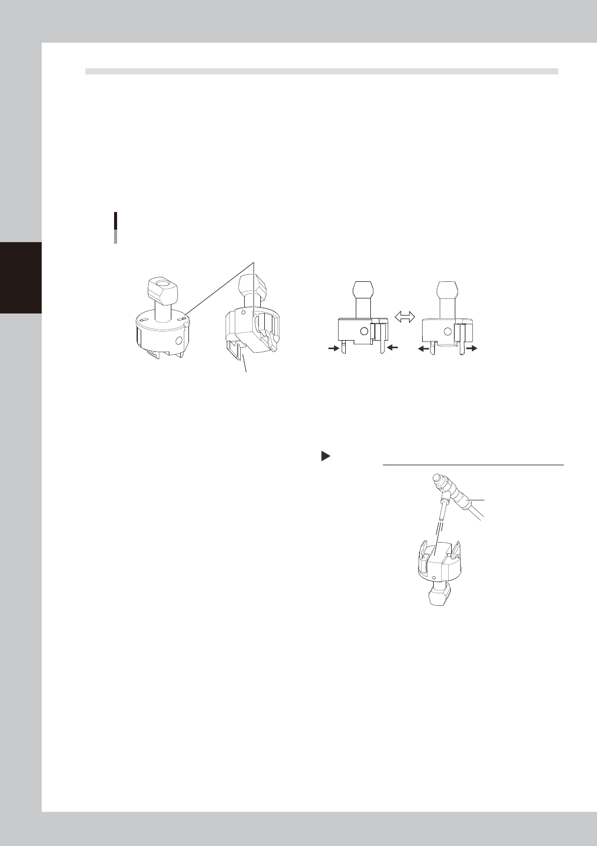
Checking the gripper nozzle condition
Move the grip of the nozzle with a finger. If it moves smoothly, there is no problem. If it moves back unsteadily
or is stuck in, the component pickup error or the recognition error may occur. Clean and lubricate the gripper
nozzle seeing the next.
Additionally, check that no wear or dirt is found in the grip or operation part. If the grip is worn out, replace
the nozzle.
Inspecting gripper nozzle
Example: Type30ALD nozzle
Grip is not worn out.
No dirt or dust is found.
Grip moves smoothly.
533A1-L4-00
1.3.2 Cleaning and lubricating the gripper nozzle
e
1
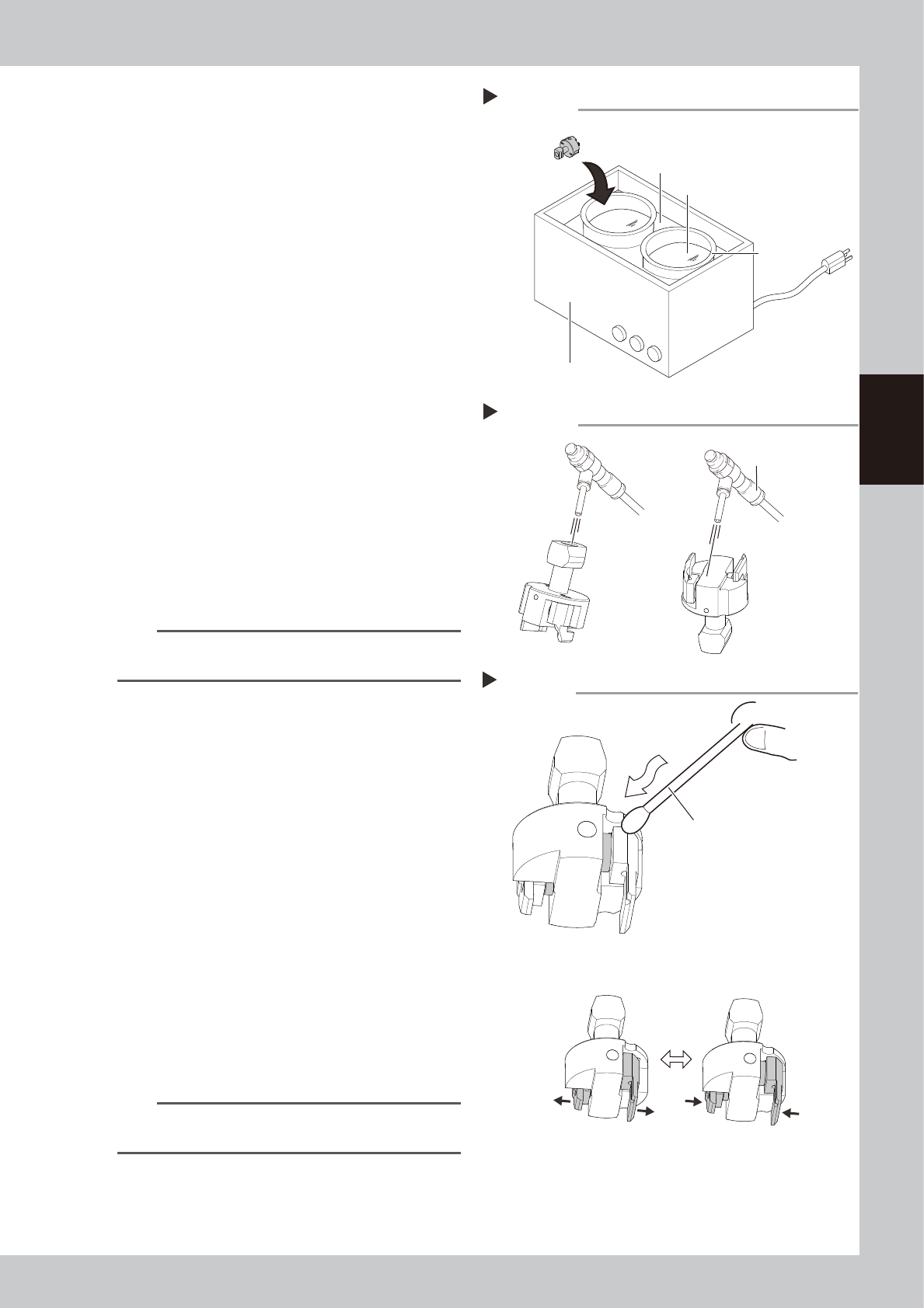
Remove nozzles.
1. Press the emergency stop button and
then open the machine safety cover.
2. Remove nozzles from the head. If the
machine is equipped with the nozzle
station, press the [Nozzle Stn Shutter]
button to open the nozzle station shutter
and remove nozzles.
2
Clean the nozzle operation part.
If dust is found in the gripper nozzle
operation part, remove it with an air blow
tool (option), etc.
533A2-L4-00
Blow
Step2
Air blow tool
3-7
3
Periodic maintenance items
3
Clean nozzles with an ultrasonic
cleaner.
1. Put nozzles into a container (such as
beaker) in an ultrasonic cleaner.
2.
Pour IPA in a container until nozzles are dipped.
3. Pour water in an ultrasonic cleaner.
4. Clean nozzles with an ultrasonic cleaner
for about 10 minutes.
533A3-L4-00
4
Blow nozzles.
1.
Take nozzles out from an ultrasonic cleaner
.
2. Air blow entire nozzle to remove IPA.
Intensively air blow the nozzle operation
part and the air path
533A4-L4-00
5
Lubricate the nozzle.
1. Apply turbine oil to a cotton swab or tip
of a precision screwdriver slightly.
2. Apply turbine oil to the nozzle operation
part.
3. Move the nozzle several times to spread
turbine oil to the nozzle operation part.
533A5-L4-00
n
NOTE
A thin coat of oil is enough to lubricate the operation
part.
6
Remove excess oil.
1. Remove excess oil by blowing the
operation part with an air blow tool.
2. Use a cotton swab or cloth to wipe away
excess oil around the operation part.
7
Check the nozzle operation.
1. Return removed nozzles to the head. If
nozzles were removed from the nozzle
station, once return them to the nozzle
station. Press the [Nozzle Change] button
to attach nozzles to the head.
2. Press the [Vacuum] button relevant to
the head on the [Unit] - [Head] screen.
Check that the gripper nozzle closes
smoothly.
3. Press the [Vacuum] button again to
cancel vacuuming. Check that the
gripper nozzle opens smoothly.
n
NOTE
If removed nozzles from the nozzle station, return them
to the nozzle storage positions.
Step3
Ultrasonic cleaner
Ultrasonic cleaner
Beaker
Pour water.
Pour IPA.
Step4
Air blow
Air blow tool
Lubricating gripper nozzle
Step 5
Apply turbine oil slightly with cotton swab
or precision screwdriver.
Spread turbine oil.
3-8
3
Periodic maintenance items
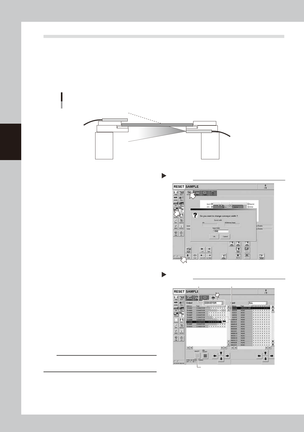
1.4 Checking the conveyor sensor condition and operation
This machine uses a transmission type fiber sensor as the conveyor sensor.
As the conveyor width changes, the distance between the light emitting and light receiving sensors also
changes. Accordingly, the light receiving status of the sensor may change.
Therefore, a conveyor sensor tuning function is provided on this machine that stores the sensor light receiving
status after the conveyor rail width has been changed and automatically rewrites the sensor threshold value.
By changing the conveyor rail width periodically, you can check that the conveyor sensors and conveyor sensor
tuning operate correctly.
Checking the conveyor sensor condition and operation
Light emitting
Light receiving
53304-L4-10
1
Opzen the [Unit] – [Conveyor]
screen.
2
Press the [Width] button to change
the conveyor width.
In the "Conveyor Width" screen that
appears, enter a conveyor width and press
[OK] button.
The conveyor is changed to the width that
was just entered.
3
Check whether an error has
occurred.
The conveyor sensor is operating properly
unless an error message appears when the
conveyor width is changed. No further
check is necessary.
If an error occurred, perform "Conveyor
sensor tuning" from Step 4.
54300-L4-10
4
Perform the conveyor sensor
tuning.
1. Open the [Unit] – [I/O] screen.
2. From the "Output" drop-down list, select
"CONVEYOR".
3. Select "CONV SENSOR TUNING" (T01000E1)
in the output I/O list.
n
NOTE
In dual-lane machines, "T01000E1" corresponds to Lane
1, and "T01000E3" to Lane 2.
4. Press the [ON/OFF] button to switch the I/
O status from "0" (OFF)
→
"1" (ON)
→
"0"
(OFF) to perform auto tuning.
54301-L4-10
Checking the conveyor sensor
Step 1-3
Conveyor sensor tuning
2
3
4
Step 4