YS24X_Mainte_E - 第80页
3-13 3 Periodic maintenance items 2. Monthly or bimonthly inspection 2.1 Cleaning the nozzle air path Clean the nozzle air path if a nozzle clogging is found in the daily inspection or every month. e 1 Remo ve the nozzle…
3-12
3
Periodic maintenance items
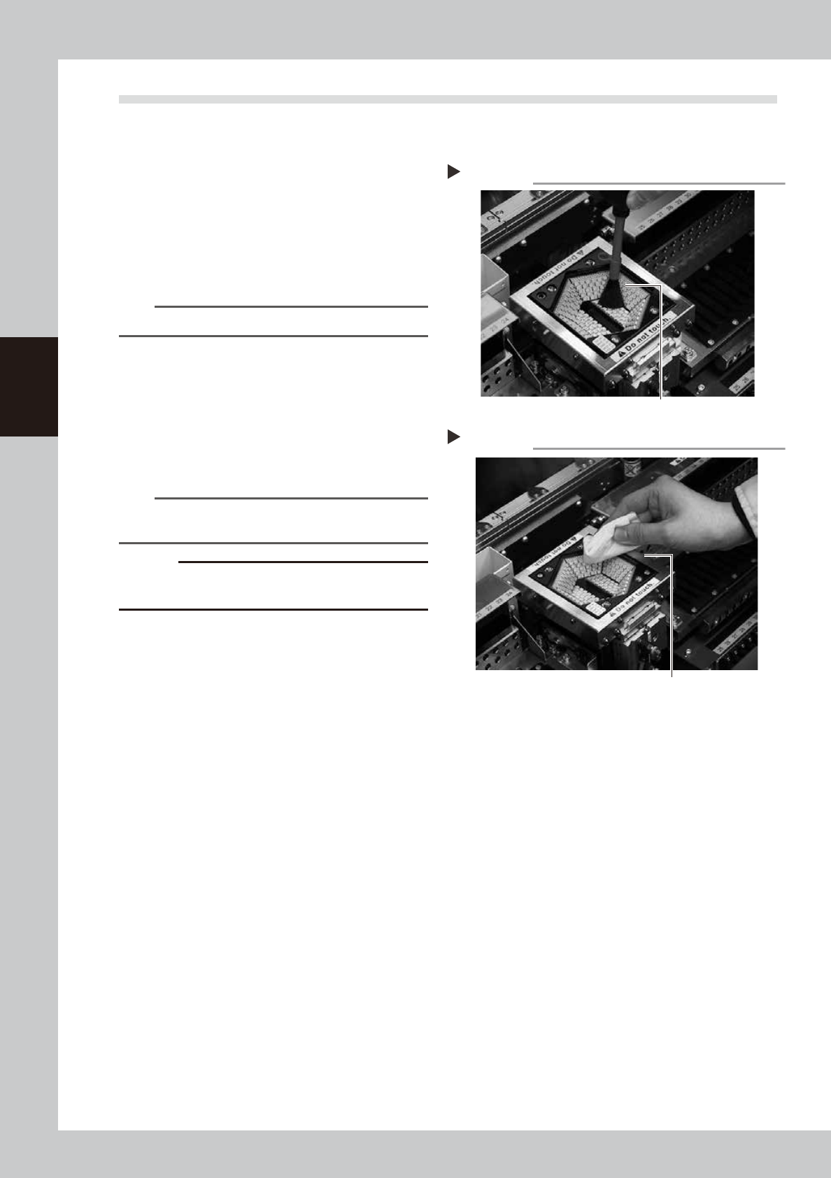
1.7 Cleaning the camera protective glass
Adhered dust, etc., on the multi-camera lighting's protective glass can cause component recognition errors.
To prevent this, it is recommended to inspect and clean the cover in a periodic manner.
e
1
Blow off dust on the lighting's
protective glass.
1. Press the emergency stop button to open
the machine safety cover.
2. Remove the dust on the lighting's
protective glass with a blower brush.
53389-L4-00
TIP
A lens blower brush is an optional purchase part.
2
Wipe the protective glass with a
cloth or cleaning paper.
Apply a few drops of lens cleaner to a
lint-free cleaning cloth or cleaning paper
that does not raise dust, and wipe the
protective glass.
53390-L4-00
n
NOTE
A lens cleaner and cleaning paper are optional
purchase parts.
c
CAUTION
Do not use other than the lens cleaner optionally
supplied, such as IPA or acetone.
Blowing off dust with blower brush
Step 1
Lens blower brush
Wiping the transparent cover
Step 2
Lent-free cleaning cloth or paper wiper
3-13
3
Periodic maintenance items
2. Monthly or bimonthly inspection
2.1 Cleaning the nozzle air path
Clean the nozzle air path if a nozzle clogging is found in the daily inspection or every month.
e
1
Remove the nozzle from the head.
1. Press the emergency stop button and
then open the machine safety cover.
2. Remove the nozzle from the head. If the
machine is equipped with the nozzle
station, press the [Nozzle Stn Shutter]
button to open the nozzle station shutter
and remove the nozzle.
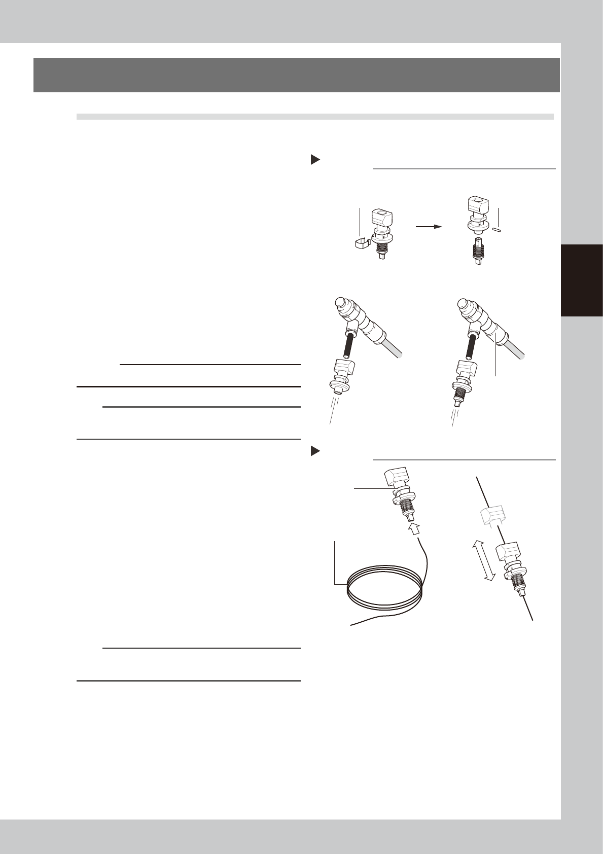
2
Blow air through the nozzle.
1. Detach the nozzle tip and air blow the
nozzle from the nozzle mounting side.
2. Attach the nozzle tip and air blow the
nozzle from the nozzle mounting side.
53308-L4-10
c
CAUTION
Be careful not to deform the clip.
n
NOTE
If there are dust deposits in the nozzle, perform steps 3
and 4.
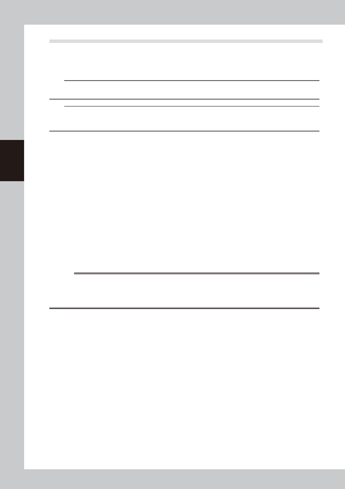
3
Clean the nozzle hole.
1. Pass a nozzle cleaning wire through the
nozzle hole.
2. Clean the nozzle by moving it as shown
at right.
53309-L4-10
4
Blow air onto the nozzle tip again.
Remove the nozzle cleaning wire, then
air-blow the nozzle interior with the air blow
tool as described in Step 2.
5
Return the nozzle to its original
head.
n
NOTE
If removed nozzles from the nozzle station, return them
to the nozzle storage positions.
Cleaning a nozzle
Step 3
Nozzle
Nozzle cleaning wire
Air blow
Step 2
Air blow unit (optional)
Remove the clip.
Pull out the pin.
Air tube (orange) connected
to air supply port
■ Detach the nozzle tip, and
air-blow from that side.
■ Attaching/detaching the nozzle tip
■ Blow air from the nozzle
attachment side.
3-14
3
Periodic maintenance items
2.2 Inspecting each axis
Inspect the ball screws on the X, W, U, and PU (Push-up) axes and the guides on the X, Y, W, and U axes. The
checkpoints are listed below.
A grease spattering prevention cover is attached to the X-axis ball screw. Before starting the inspection work,
detach this grease spattering prevention.
TIP
See "3.1 Cleaning and greasing the X and Y axes" described later on for detaching or attaching the anti grease
splatter cover.
TIP
See "3.1 Cleaning and greasing the X and Y axes", "3.2 Cleaning and greasing the push-up axis (PU-axis)", "4.7 Dual
stage only: Cleaning and lubrication of U axis (W2 axis)" and "5.2 Cleaning and lubricating the W-axis" in this chapter,
and "Chapter 5 Lubrication points and schedule" for positions of ball screws and guides of each axis.
Checkpoints
1. Any foreign matter adhering to the ball screws and guides?
Check if any fallen chips have adhered to the X and Y axis ball screws and/or X, Y and W axis guides.
2. Do the ball screws and guides have the correct amount of grease?
Check if grease has flowed off or splattered in the air failing to adhere. Also check if grease has discolored or hardened.
e
3. Any abnormal sounds from the ball screws?
Press the emergency stop button. Then check for any abnormal sounds while pressing the X-axis by hand.
Countermeasures
1. Ball screws and guides may be damaged when chips and other material bite into them. If chips are adhering, wipe
them off along with the grease or remove with tweezers, etc.
2. Apply grease referring to "3.1 Cleaning and greasing the X and Y axes", "3.2 Cleaning and greasing the push-up axis
(PU-axis)", "4.7 Dual stage only: Cleaning and lubrication of U axis (W2 axis)" and "5.2 Cleaning and lubricating the
W-axis" in this chapter described later on.
3. Contact YAMAHA sales representative when abnormal sounds occur even after trying the countermeasures in the above
steps 1 and 2.
w
WARNING
THIS MACHINE CONTAINS PARTS GENERATING STRONG MAGNETIC FIELDS. GREAT CARE SHOULD BE TAKEN WHEN A PART
OF YOUR BODY IS PUT INSIDE THE MACHINE FOR THE MAINTENANCE WORK. CAUTIONS REGARDING FERROMAGNETIC
FIELDS ARE DESCRIBED IN THE SECTION, "SAFETY INSTRUCTIONS", AT THE BEGINNING OF THIS DOCUMENT. ALWAYS
THOROUGHLY READ THIS SECTION TO FULLY UNDERSTAND ITS CONTENTS.