YS24X_Mainte_E - 第92页
3-25 3 Periodic maintenance items 6 Set the applied grease. 1. Close the machine’s safety cover , and cancel the emergency stop. If the machine could be equipped with a carriage, set the carriage. 2. Press the [Pushup] b…
3-24
3
Periodic maintenance items
3.2 Cleaning and greasing the push-up axis (PU-axis)
The push-up axis is designed to prevent flexing or warping of the board during clamping and is important
because it prevents depressing of the board during component mounting.
The PU axis also prevents deviations in the component mounting accuracy due to the board depressing during
component mounting, so it is important to regularly clean and inspect the PU axis to ensure it operates
correctly.
c
CAUTION
If trouble occurs with the PU axis, then contact YAMAHA sales representative. Disassembly and cleaning of the PU axis
by the user will void the warranty.
1
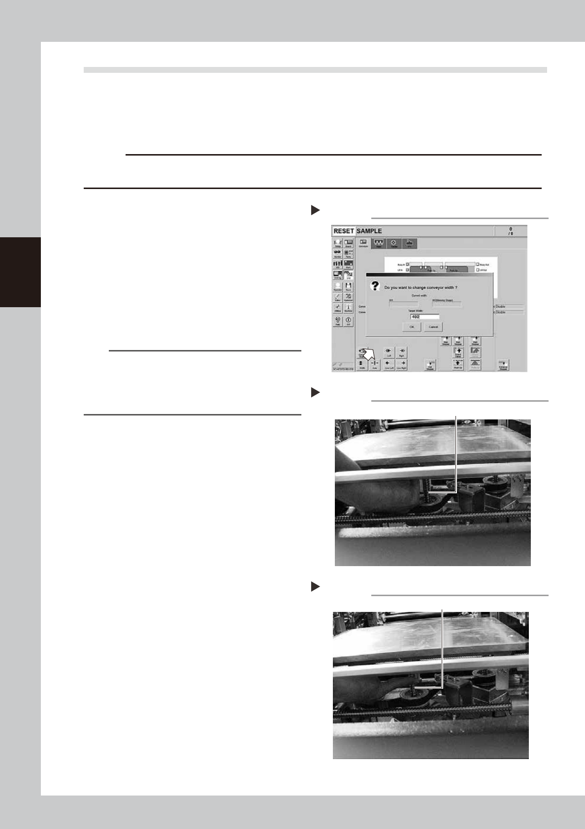
Set the conveyor width to
maximum.
1. Press the [Conveyor Width] button on the
[Unit] – [Conveyor] screen to display the
Conveyor Width Change screen.
2. Enter the maximum with described in the
specification in [Conveyor Width after
Change], and press the [OK] button. The
conveyor width changes to the specified
width.
54303-L4-10
TIP
The maximum width of dual stage and single lane
specification conveyor width is 460 mm. If the
specification is the dual lane, enter 382 mm as the
maximum width in Lane 1 or Lane 2 in order to match
the pushup axis position of lubrication target.
2
Raise the push-up unit.
1. Press the [Pushup] button on the stage or
lane to conduct grease up to display the
“Conveyor Pushup” screen.
2. Enter “0.1 mm” in Thickness and press the
[OK] button. The pushup unit moves up.
3
Make the preparations for the
cleaning and greasing work.
e
1. Take off all accessories susceptible to the
magnetic fields, such as a wristwatch
and/or magnetic ID card.
2. Press the emergency stop button and
then open the machine safety cover.
3. If the machine is equipped with a
carriage, remove the carriage to make
the pushup unit easy to access.
4
Wipe the old grease.
Wipe the old grease on ball screws (3
locations) with a lint-free cloth that does not
raise dust.
53328-L4-00
5
Apply the new grease.
Apply as much as 2 cm of specified grease
(NSL) to finger. Rub it evenly into the ball
screw grooves.
53329-L4-00
Cleaning the ball screw
Step 4
Ball screw (3 places)
Applying the grease
Step 5
Ball screw
Setting the conveyor width
Step 1

3-25
3
Periodic maintenance items
6
Set the applied grease.
1. Close the machine’s safety cover, and
cancel the emergency stop. If the
machine could be equipped with a
carriage, set the carriage.
2. Press the [Pushup] button on the stage or
lane that grease up was conducted to
lower the pushup unit.
3. Follow the Step 2 procedure to raise the
push-up unit.
4. Repeat Step 2 and 3 several times to set
the grease. After setting the grease,
leave the push-up unit in the up state.
e
7
Wipe away excess grease.
1. Press the emergency stop button, and
open the machine’s safety cover. If the
machine is equipped with a carriage,
remove the carriage.
2. Wipe the excess grease with lint-free
cloth that does not raise dust.
3-26
3
Periodic maintenance items
3.3 Inspecting and cleaning the conveyor belt
Inspect the conveyor belt for wear. As the belt wears away, slippages may occur that prevent securely
conveying the boards. It is therefore necessary to make periodic checks for wear of the conveyor belt.
Belt wear may also cause trouble such as erroneous detection of the conveyor sensor due to dust from belt
wear accumulating on the sensor surface, or dust from belt wear accumulating in the belt guide grooves may
cause the belt to stick, etc.
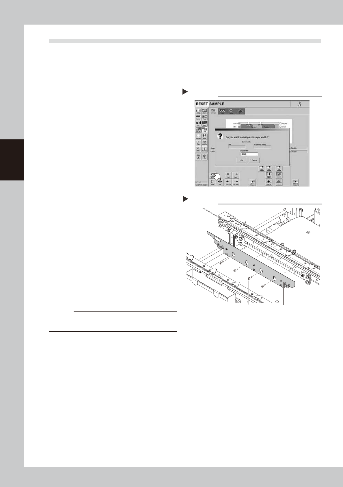
1
Change the conveyor width to a
convenient width for maintenance
work.
1. Press the [Width] button to display the
"Conveyor Width" screen.
2. Enter a width wide enough for a hex
wrench to be inserted (about 200 mm) in
the "Target Width" box and press the [OK]
button. The conveyor is changed to the
specified width.
54304-L4-10
2
Make the preparation for cleaning.
e
1. Remove all items that are affected by
magnetism, such as a watch and ID
card.
2. Press the emergency stop button and
then open the machine safety cover.
3. Lower the feeder exchange carriage by
using the clamp switch and remove the
feeder exchange carriage.
4. Place a square cloth on the push-up
plate.
3
Remove the board clamp plates.
Use a hexagon wrench (3) to remove the 4
board clamp bolts, then remove the board
clamp plate.
533D1-L4-00
c
CAUTION
Do not remove any bolts other than the 4 bolts shown in
the figure at right.
Removing the board clamp plate
Step 3
Board clamp plateBoard clamp plate securing bolts
Changing the conveyor width
Step 1