CP-642ME-06.pdf - 第5页
1. 部品は、図番、コ−ド番号、個数、品名、および規格で発注下さい。 この発注方法以外で発注された場合は発注部品に間違いが生じる恐れがあります。 ※シリアルNo.をご確認の上、お問い合わせ下さい。 2. 本パ−ツリストは改良のため予告なく変更することがあります。 3. リスト左端の番号が抜けて順番に記載されていない箇所がありますが、これは記載モレや作成途中ではなく、 今まで使用していた部品が設計変更 により使用されなくなり表から削除され…
1. Specify a part number, code number, quantity, part name and rating when ordering parts.
Ensure to check the serial number of your machine before contacting Fuji.
2. This parts manual is subject to change without notice.
3. There are cases where there are no numbers in the left hand column of the parts list. This is not because they were omitted or
the list is incomplete but because the parts to which the numbers applied were eliminated due to a design change.
In such cases the parts have also been removed from the figures.
4. Only the part types are described for nuts, bolts and washers. The quantity column is left blank.
5. A redesigned part (the last digit of the part number is incremented) is compatible with a part before the redesign.
However,the original part is not always compatible with the revised part,e.i.,ABC1231 is compatible with ABC1230,but
ABC1230 is not always compatible with ABC1231.
6. The characters in the “Materials” field of the list are abbreviations for the following materials.
FE: Iron CO: Copper OT: Other
AL: Aluminum PL: Plastic
7. Standard torque levels should be applied when tightening bolts during maintenance. For those areas requiring non-standard
levels of torque or adhesive, the torque levels and glue maker and name are detailed on those pages indicated with a spanner
mark in the bottom left hand corner.
(N・m)
Standard torque Chart
M2.0 M2.5 M3 M4 M5 M6 M8 M10 M12 M16 M18 M20
鉄 0.44 0.88 1.96 3.92 7.84 12.74 32.34 64.68 117.6 303.8 401.8 588
アルミ 0.35 0.78 1.47 3.23 5.88 9.31 18.62 37.24 42.14 88.2 98 117.6
・ 1Kgf・㎝≒0.098N・m
・ 1Kgf・㎝≒9.8N・㎝
・ 1N・m≒10.2Kgf・㎝
SPANNER MARK
Blueprints created : MAR 2003
06JE released : MAY 2002
Before Using The Parts List
NEXT

1. 部品は、図番、コ−ド番号、個数、品名、および規格で発注下さい。
この発注方法以外で発注された場合は発注部品に間違いが生じる恐れがあります。
※シリアルNo.をご確認の上、お問い合わせ下さい。
2. 本パ−ツリストは改良のため予告なく変更することがあります。
3. リスト左端の番号が抜けて順番に記載されていない箇所がありますが、これは記載モレや作成途中ではなく、 今まで使用していた部品が設計変更
により使用されなくなり表から削除されたものです。同時にイラスト内の部品も削除されています。
4. ボルト類,ナット類およびワッシャ類などは種類のみ記載してあります。それぞれの個数は記載せず空欄となっています。
5. 設計変更した部品(図番の下一桁をカウントアップした部品)は設計変更前の部品と互換です。
しかし、設計変更前の部品は設計変更後の部品と互換であるとは限りません。
例:ABC1231はABC1230と互換であるが、ABC1230がABC1231と互換であるとは限りません。
6. リスト欄の材質はFE(鉄系),AL(アルミ系),CO(銅系),PL(プラスチック系),OT(左記以外)を示します。
7. メンテナンス作業でボルト等を締付ける場合は下記一般締付けトルク表をご利用下さい。但し、一般ではない締付けトルク管理、接着剤管理が
必要な箇所については、特別に左下スパナマークの付いたイラストページ(トルク値、接着剤名&型番)を各ユニット毎に追加しましたので
ご参照下さい。
(N・m)
一般締付けトルク表
M2.0 M2.5 M3 M4 M5 M6 M8 M10 M12 M16 M18 M20
鉄 0.44 0.88 1.96 3.92 7.84 12.74 32.34 64.68 117.6 303.8 401.8 588
アルミ 0.35 0.78 1.47 3.23 5.88 9.31 18.62 37.24 42.14 88.2 98 117.6
・ 1Kgf・㎝≒0.098N・m
・ 1Kgf・㎝≒9.8N・㎝
・ 1N・m≒10.2Kgf・㎝
スパナマーク
図面原稿 : 2003年 3月
06JE発行 : 2003年 5月
パ−ツリストをご利用される前に
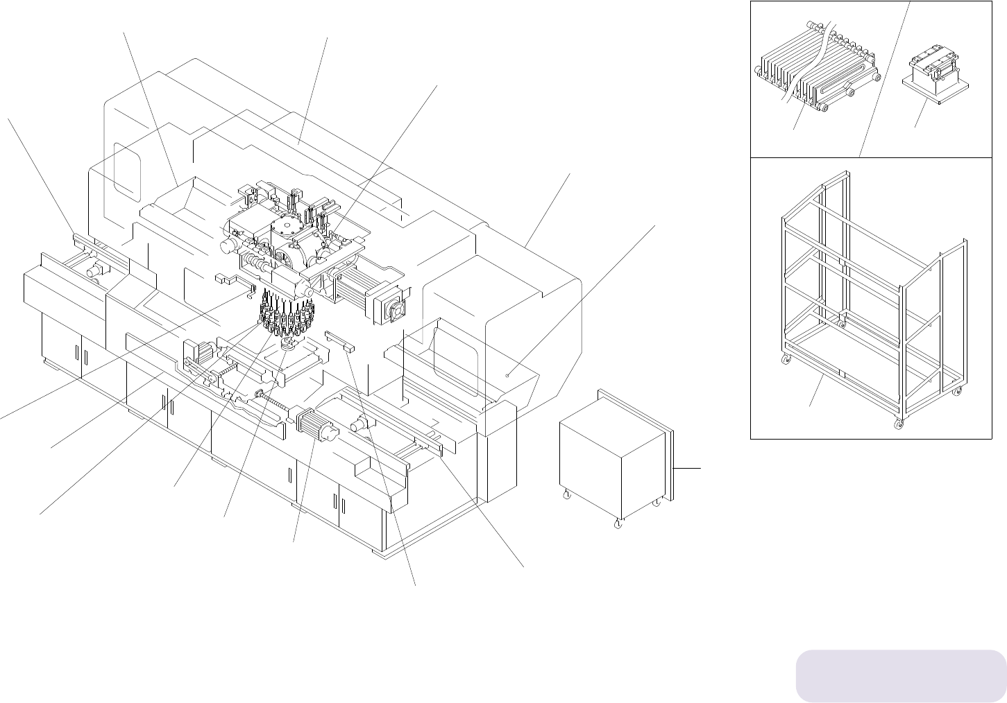
CP-642ME 配置図
CP-642ME Overview
配置番号は目次番号です。
Refer to contents for
the part name of each number
Ref.33-7
Ref.31-1
Ref.31-1
Ref.31-1
Ref.31-1
0.5 1 2 10
タテx173.205
208
176
165
175
161
175
161
175
161
183
162
176
167
175
161
13
13
B
A
139
26
x15
16
Body
29.−−−−−−− 本体
Fence
40−1,40−2−−フェンス
Air
28,31.−−−− エア−
Cover
30.−−−−−−− カバ−
29.−−−−−−− シャッタ−
Shutter
41−1,41−2−−英国フェンス
UK Fence
1.1.Nozzles
1.2.Nozzles
2.Placung head,drum
5.Loading unit
11.Feedr check sensor
21.Device table D2
20.Device table D1
10.Optical correction
23.1.Noise reduction box
23.2.Noise reduction box
25.Cam box 1
26.Cam box 2
27.1.Cam box 3
27.2.Cam box 3
22.1.Noise reduction cover
22.2.Noise reduction cover
22.3.Noise reduction cover
11.Feedr check sensor
24.Dust collector
12.ST 1(Parts pick up)
13.ST 2(Parts check)
14.ST 5(Nozzle theta positioning)
15.1.ST 6(Vision processing)
15.2.ST 6(Vision processing)
16.ST 10(Fine theta),ST 12(Reverse fine theta)
17.ST 3(Pre theta),ST 13(Reverse pre theta)
18.ST 16(Parts eject),Wast tape sutter
19.ST 17(Nozzle pre chang check),
ST 18(Nozzle chang),
ST 19(Nozzle post chang check)
CP−642ME 配置図 Overview
4.Out conveyor
33.In conveyor(R→L)(Option)
35.Out conveyor(L→R)(Option)
44.Out conveyor(Cover)(Option)
28.Pneumatic circuit diagram
29.Body
30.Cover
31.Air device
39.Shutter(Option)
40.1.Fence(Option)
40.2.Fence(Option)
41.1.UK fence(Option)
41.2.UK fence(Option)
45.Standard accessory,Tool
6.1.Board clamping unit
6.2.Board clamping unit
6.3.Board clamping unit
7.X slide
8.1.Y slide
8.2.Y slide
9.1.Z table
9.2.Z table
42.Vacuum back up
37.Cartridge rack
36.Cartridge stand
38.Feeder setting jig
3.In conveyor
32.Out conveyor(R→L)(Option)
34.In conveyor(L→R)(Option)
43.In conveyor(Cover)(Option)