Micron Technical Reference V9 Volume 1.pdf - 第102页
PRINTER OVERVIEW MODULE OVERVIEWS 4.8 Technical Reference Manual Chapter Issue 11, Jan 17 Dual Lane The dual lane printer consists of two sets of transport rails, one being a print lane and the other being a pass through…
PRINTER OVERVIEW
MODULE OVERVIEWS
Chapter Issue 11, Jan 17 Technical Reference Manual 4.7
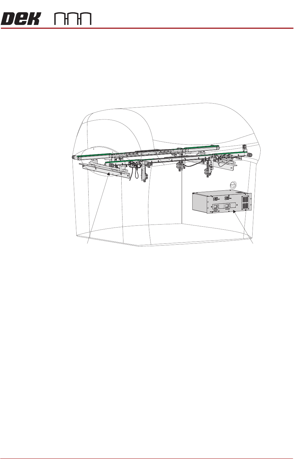
High Throughput
Conveyor Module
The high throughput conveyor (HTC) module is an optional programmable width
conveyor system. The function of the HTC is to transport up to three boards
through the printer at one time using belts. The rail system height is positioned
by the rising table, during the print cycle. Two systems are currently available,
the standard HTC system and the MHTC. MHTC is a modular transport rail
system for the HTC. It has a modular centre section, which can give support to
a variety of clamping arrangements.
Figure 4-9 High Throughput Conveyor (HTC)
HTC Module
M27 HTC Controller Enclosure
PRINTER OVERVIEW
MODULE OVERVIEWS
4.8 Technical Reference Manual Chapter Issue 11, Jan 17
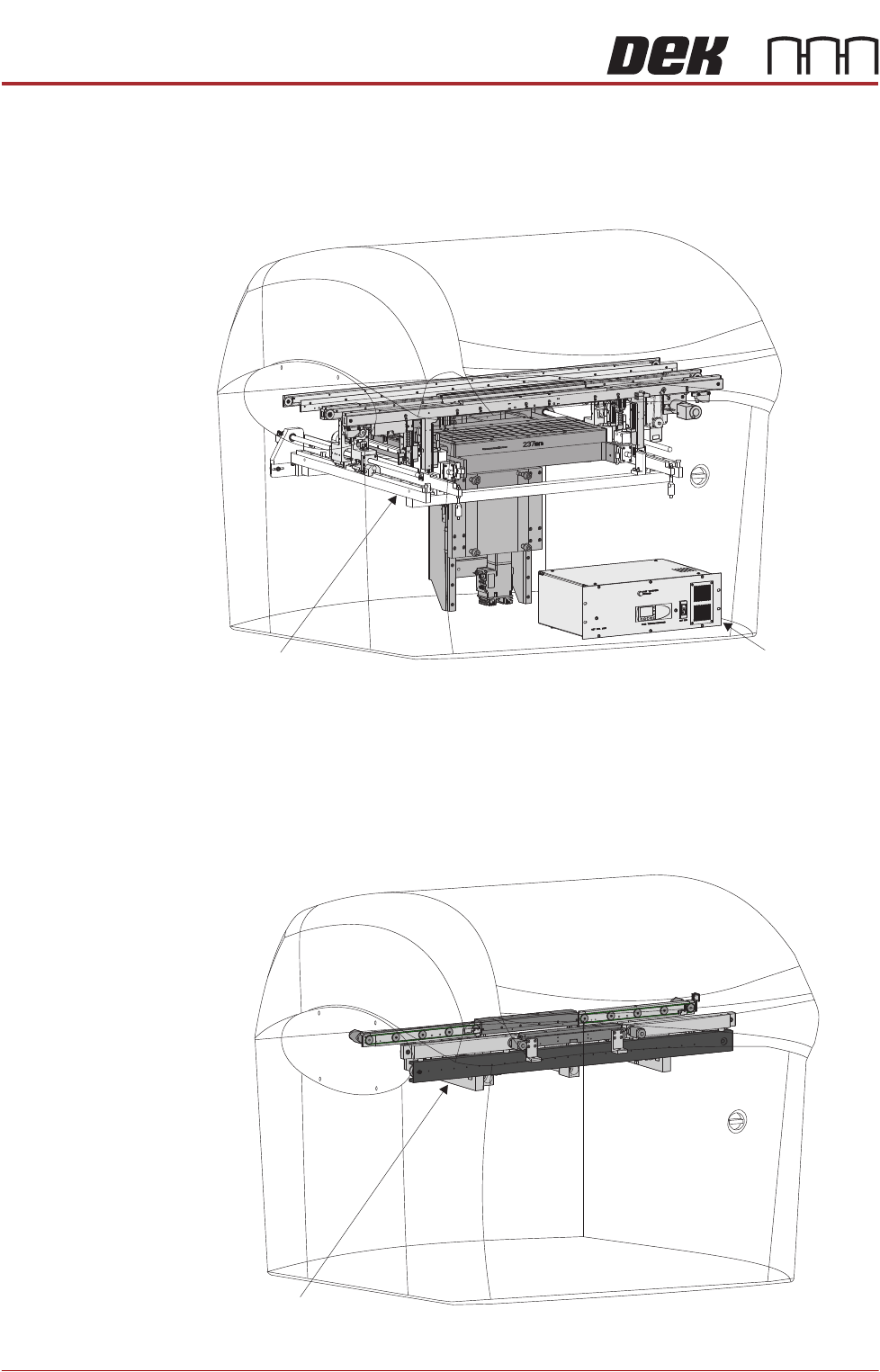
Dual Lane The dual lane printer consists of two sets of transport rails, one being a print
lane and the other being a pass through lane. The printers are a dedicated build
and available as a front print or rear print printer. Dual lane is not an option that
can be fitted to a standard printer.
Figure 4-10 Dual Lane
Rapid Transit
Conveyor (RTC)
The RTC is a programmable width, 3 stage, conveyor system which sets the rail
width and transports boards through the printer using belts and vanes. The
system can accommodate up to three boards in the printer at one time thereby
reducing the printer cycle time. RTC printers are a dedicated build, it is not an
option that can be fitted to a standard printer.
Figure 4-11 Rapid Transit Conveyor
Dual Lane Module
M40 Dual Lane Controller
RTC Module
PRINTER OVERVIEW
MODULE OVERVIEWS
Chapter Issue 11, Jan 17 Technical Reference Manual 4.9
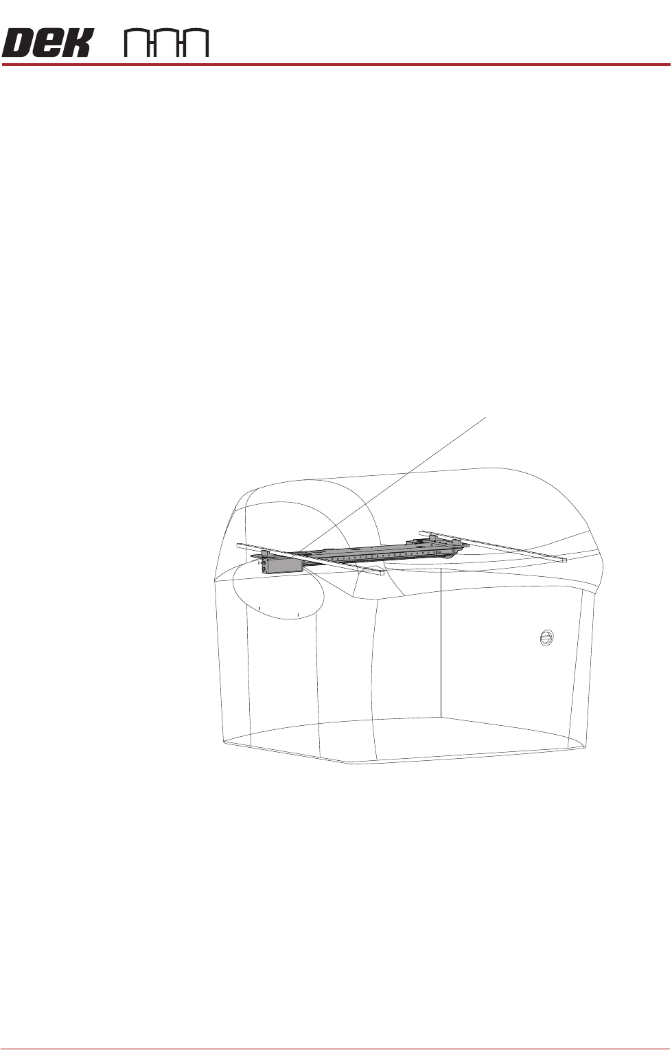
Camera System
Module
The function of the camera system is to supply a visual indication of stencil to
board alignment and board/stencil inspection data to the printer PC enclosure.
The captured information supplied to the PC enclosure enables the processor
to:
• Align the stencil to the product board
• Provide visual information for the user on the MMI monitor
The camera assembly traverses horizontally in the X and Y axis and is driven
by either:
• Rotary Servo Motors
• Linear Servo Motors
The camera carriage is also used to transport the board stop and the under-
screen cleaner.
Figure 4-12 Camera System
Camera System