Micron Technical Reference V9 Volume 1.pdf - 第110页
PRINTER OVERVIEW MODULE OVERVIEWS 4.16 Technical Reference Manual Chapter Issue 11, Jan 17 Foreign Machine Interface (FMI) Module The FMI provides a communications link between uplin e/downline machines and the DEK print…
PRINTER OVERVIEW
MODULE OVERVIEWS
Chapter Issue 11, Jan 17 Technical Reference Manual 4.15
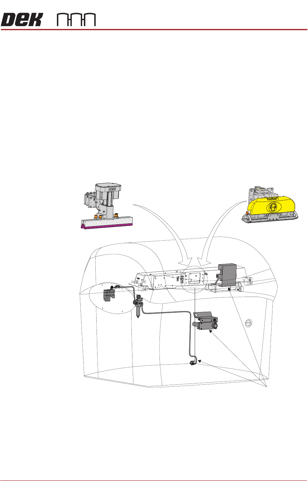
Pneumatics
Module
The function of the pneumatics module is to supply regulated air pressure to the
pneumatic devices throughout the printer. The air supply is routed to the
required pneumatic device via an electrically operated solenoid valve controlled
by the printer control system.
There are two banks of pneumatic solenoids, one located on the rear frame of
the printer and the other located on the print carriage.
Squeegee Module The function of the squeegee module is to apply the print material through the
stencil image onto the board in a controlled manner. Squeegee height and
downward pressure is monitored during the print stroke to optimize the print
quality.
ProFlow Module The ProFlow module is an optional self contained paste transfer unit, employed
to apply print material directly to a stencil, alleviating the need for squeegees
and the paste dispenser.
Figure 4-18 Pneumatics - Squeegee - ProFlow
Squeegees
ProFlow
Pneumatics
PRINTER OVERVIEW
MODULE OVERVIEWS
4.16 Technical Reference Manual Chapter Issue 11, Jan 17
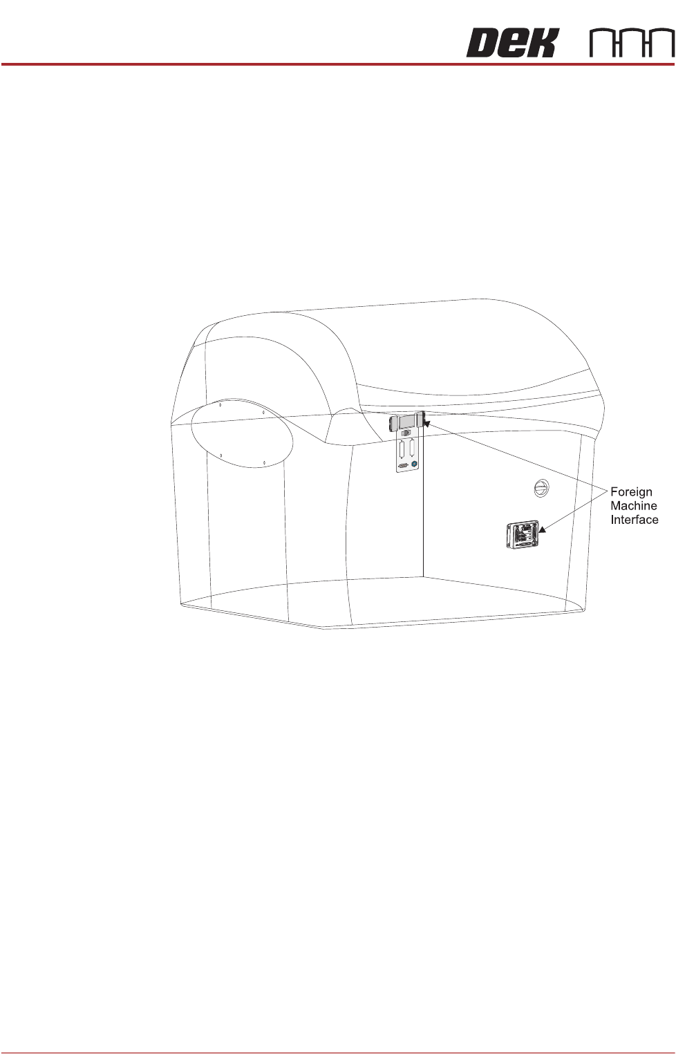
Foreign Machine
Interface (FMI)
Module
The FMI provides a communications link between upline/downline machines
and the DEK printer.
The FMI pod, fitted to the rear of the printer, is used to communicate with upline/
downline machines using SMEMA, Fuji or Panasonic interfaces.
NOTE
Type 4 printers, the FMI pod is accessed from the front of the printer.
The Multi-Interface Unit (MIU), fitted inside the front cover of the printer, is used
to communicate with upline/downline machines using all other protocols.
Figure 4-19 Foreign Machine Interface

PRINTER OVERVIEW
MACHINE PRINT CYCLE
Chapter Issue 11, Jan 17 Technical Reference Manual 4.17
MACHINE PRINT CYCLE
The following, is a typical machine print cycle (RS transport rail system), with
camera mounted board stop and squeegees/paste dispenser used as the paste
applicator system:
1. Print is selected, the printhead cover lock is engaged and the rising table
carries out a rail lifted check.
2. The camera positions itself at the board stop co-ordinates.
3. The print carriage moves to the start of the print stroke and both squeegees
drive to their set dwell height. The chase clamps are applied clamping the
chase in position.
4. The board is transported into the printer stopping at the board stop.
5. The transport belts stop running as soon as the board stop sensor detects
the board.
6. The board clamp mechanism operates, clamping the board in position and
the board stop retracts.
7. The camera carriage drives to the position determined by Fiducial 1 X & Y
co-ordinates.
8. The print carriage is driven to its enhanced start position and the appropriate
squeegee is driven down to start height.
9. The rising table carries out a rail lift check and drives up to vision height.
10. The vision data window displays the board fiducial on the left and the stencil
fiducial on the right of the split display.
11. The fiducials are located and a small blue cross with the fiducial outline
appears in the centre of each fiducial on the split display indicating success-
ful location.
12. While the camera drives to Fiducial 2 X and Y coordinates, the location of
the Fiducial 1 board and stencil fiducials are copied to the align data
structure.
13. Fiducial 2 board and stencil fiducials are located.
14. The chase clamps are de-energised and the stencil actuators carry out a
rough alignment on the stencil. The chase clamps are re-applied securing
the stencil.
15. The camera relocates Fiducial 1 and 2 On completion, the camera carriage
drives to its home position.
16. The chase clamps are de-energised and fine alignment on the stencil is
carried out. On completion, the chase clamps are re-applied.
17. The relevant squeegee is driven down to make contact with the stencil with
0.5kg force.
18. The rising table drives up to the print height.
19. The appropriate squeegee is driven down to the calculated pressure setting,
as set in the board parameter menu.
20. The print carriage drives in the appropriate direction to perform a print
stroke.
21. The squeegee mechanism releases full pressure but keeps the squeegee