Micron Technical Reference V9 Volume 1.pdf - 第121页
POWER SUPPLY M37 ELECTRICAL SCHEMATIC Chapter Issue 13, Jan 17 Technical Reference Manual 5.7 ELECTRICAL SCHEMA TIC M 37 Power Su pp ly Crate CB 32 10A PSU + 24V -12V + 12V + 5.5V Internal V ac Pump CB34 16A TB2 TB3 L N …

POWER SUPPLY M37
OVERVIEW
5.6 Technical Reference Manual Chapter Issue 13, Jan 17
WARNING
LETHAL VOLTAGE. DANGEROUS VOLTAGES EXIST IN THIS EQUIPMENT.
ENSURE ALL ELECTRONIC COVERS AND MAIN MACHINE COVERS ARE FITTED
BEFORE OPERATING THIS EQUIPMENT.
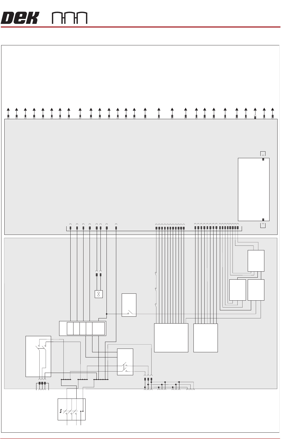
Mains input power (100V to 240V) to the machine is routed to the mains isolator
switch at the front of the machine. From the mains isolator it is fed to the M37
power supply crate, through the cable gland at the rear panel, to the three
terminal blocks TB1 (live), TB2 (neutral) and TB3 (earth). From the terminal
blocks mains power is supplied to the following:
• M37SK31 PC Supply
• M37SK32 Monitor Supply
• M37SK33 Spare
• M37SK34 Spare
• M37SK35 Internal Vac Pump via Mains Filter and CB34
• PSU
The PSU is a Switched Mode Power Supply Unit (SMPSU) which converts the
ac into the following dc supplies:
•+24V US
• +24V SW
•+5.5V
•+12V
•-12V
•+42V
• +48V (See note)
NOTE
The PSU upper voltage is set to +42V except for Type 1 machines that are set
to +48V.
The dc supplies from the PSU are fed to the power distribution PCB. Mounted
on the power distribution PCB is the PSU monitor board which enables moni-
toring of the power supplies.
An E Stop loop, front cover interlock, rear cover interlock/interlock blanking plug
and E Stop relay are fitted to ensure motor power is removed if the front
printhead cover or rear cover is opened or the machine is crash stopped by
pressing an E Stop button.
A two handed safety relay, left jog button and right jog button are fitted to enable
certain functions to be performed with the front printhead cover open.
The M37 power supply crate has mains power available; when access to the
components of the enclosure is required, observe the following warning:
POWER SUPPLY M37
ELECTRICAL SCHEMATIC
Chapter Issue 13, Jan 17 Technical Reference Manual 5.7
ELECTRICAL SCHEMATIC
M37 Power Su
pply Crate
CB 32
10A
PSU
+24V
-12V
+12V
+5.5V
Internal Vac Pump
CB34
16A
TB2
TB3
L
N
E
Mains Isolator
TB1
M37SK31
PC Supply
M37SK32
Monitor Supply
M37SK33
Spare
M37SK34
Spare
M37SK35
Internal Vac Supply
CB33
10A
2 Handed
Safety Relay
PIHZ X1
RL2
E Stop Relay
PNOZ X2
RL1
M37TB01
Power Distri
bution PCB
M37SK36
Part
CON1
Part
CON2
Part
CON3
CON 1
CON 3
CON 2
Fan
PSU Monitor Board
M37PL28
M37PL29
MMI
M37SK27
Safety I/O
M37PL26
M37SK24
E Stop Blanking Plug
M37SK30
USB Port
M37SK23
Rear Cover Interlock -
Interlock Blanking Plug
M37SK22
Front Cover Interlock
M37SK21
Spare Servo Motor Power
M37SK20
RTC I/O Node 11
M37SK19
Camera Y I/O Node 9
Servo Motor Power
M37SK18
Camera X I/O Node 8
Servo Motor Power
SpareM37SK01
Rising Table I/O Node 6
Servo Motor Power
M37SK16
M37SK17
Print Carriage I/O Node 7
Servo Motor Power
Low Current DCM37SK02
High Current DC
M37SK03
Machine I/O Node 2
M37SK04
Print Carriage I/O Node 3
M37SK05
USC I/O Node 4
M37SK06
Not Used
M37SK07
Paste Dispense I/O Node 10
M37SK08
HTC M27 - RTC I/O Node 12 -
Dual Lane I/O Node 15
M37SK09
Grid-LokM37SK10
Internal Lighting & Ionizer
M37SK11
+12V Spare
M37SK12
Remote Barcode Reader
M37SK13
Hand Held Barcode Reader
M37SK14
Machine Fans
M37SK15
M37SK25
E Stop Buttons
+ V42
/+48V
POWER SUPPLY M37
M37 POWER SUPPLY ENCLOSURE
5.8 Technical Reference Manual Chapter Issue 13, Jan 17
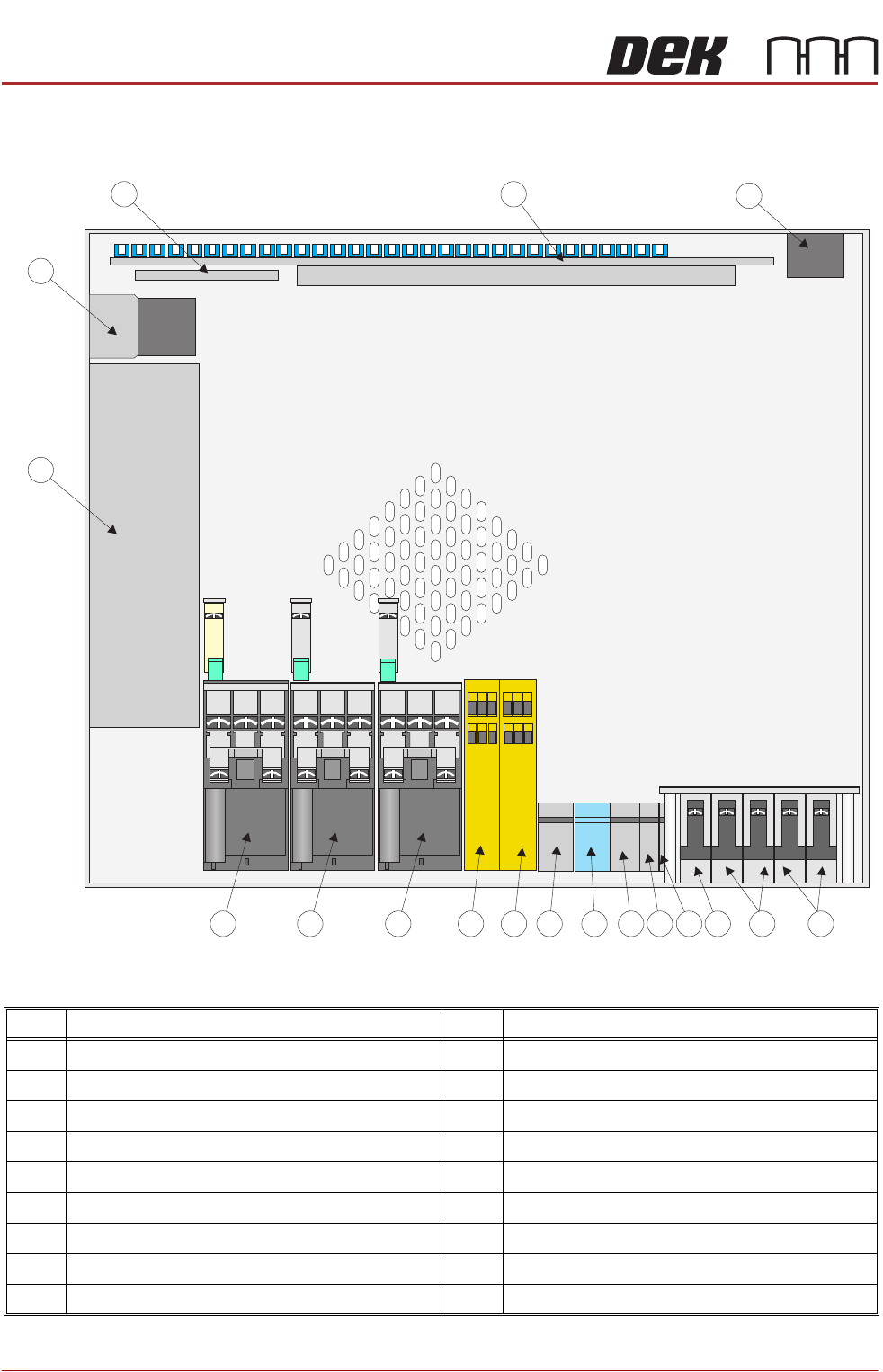
M37 POWER SUPPLY ENCLOSURE
Figure 5-6 M37 Power Supply Enclosure Layout - Plan View
Item Description Item Description
1 Mains Power Output Sockets 10 E Stop Relay
2 Circuit Breaker CB34 11 2 Handed Safety Relay
3 Circuit Breaker CB33 12 Contactor Con 1
4 Circuit Breaker CB32 13 Contactor Con 2
5 Terminal Block TB5 14 Contactor Con 3
6 Terminal Block TB4 15 Power Supply Unit PSU
7 Terminal Block TB3 16 Internal Vacuum Pump Mains Filter
8 Terminal Block TB2 17 PSU Monitor Board
9 Terminal Block TB1 18 Power Distribution PCB
1
2
3
4
5
678
910
11
12
1817
16
15
1314