Micron Technical Reference V9 Volume 1.pdf - 第127页
POWER SUPPLY M37 M37 POWER SUPPLY ENCLOSURE Chapter Issue 13, Jan 17 Technical Reference Manual 5.13 3. On the taskbar , select Start, Programs, DEK Power Monitor . The following window is displayed: NOTE Ensure that the…
POWER SUPPLY M37
M37 POWER SUPPLY ENCLOSURE
5.12 Technical Reference Manual Chapter Issue 13, Jan 17
By pressing and releasing the system switch, the relay control circuit enables
the activation of the 24V switching contacts and power is available to contactors
Con 1, Con 2 and Con 3. Contactor Con 2, via contactor Con 3, enables system
power to be available and this is signalled to the control enclosure with the
switching on of Q1. With the 24V SW supply now available, the system lamp
comes on and stays on even though the system switch has been released.
Contactor Con 2, via contactor Con 3, also enables the 42V dc or 48V dc servo
motor supply.
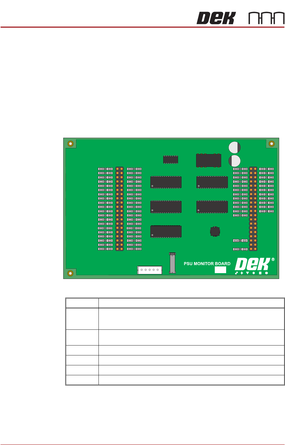
PSU Monitor Board The board monitors the voltages at circuit breakers CB1 to CB31 on the power
distribution PCB and sends a data stream via the USB port M37SK30 to the
machine PC.
The voltages monitored and where used are as follows:
A separate application is used to display the voltage readings on the machine
monitor, to access this window carry out the following:
1. Switch ON and initialise the machine.
2. On the keyboard, press the Windows key to access the taskbar.
181507 ISSUE
Voltage Where Used
+24V US NextMove Interface, MIU, Camera Lighting, Stepper Logic, Machine Fans, I/O
Node Power, Grid-Lok Tooling, High Throughput Conveyor (HTC), Euroflex and
Servo Motor Logic.
+24V SW NextMove Interface, MIU, Belt Motors, I/O Node Power, Grid-Lok Tooling and
High Throughput Conveyor (HTC).
+5.5V NextMove ES, USB Hub
+12V I/O Node Power, Grid-Lok Tooling and High Throughput Conveyor (HTC).
-12V NextMove ES
+42V/+48V Servo Motor Supply
POWER SUPPLY M37
M37 POWER SUPPLY ENCLOSURE
Chapter Issue 13, Jan 17 Technical Reference Manual 5.13
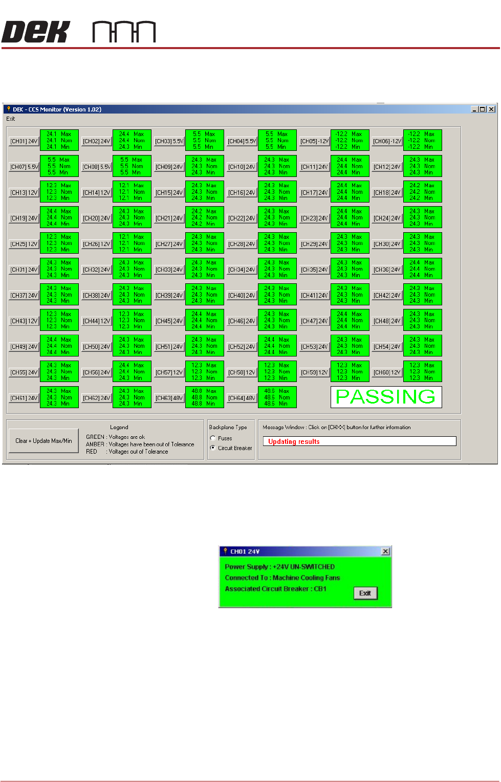
3. On the taskbar, select Start, Programs, DEK Power Monitor. The following
window is displayed:
NOTE
Ensure that the Circuit Breaker radio button is checked in Backplane Type.
4. Clicking on the channel ID button, ie (CH01) 24V, opens a further informa-
tion window, an example of which is shown below:
POWER SUPPLY M37
M37 POWER SUPPLY ENCLOSURE
5.14 Technical Reference Manual Chapter Issue 13, Jan 17
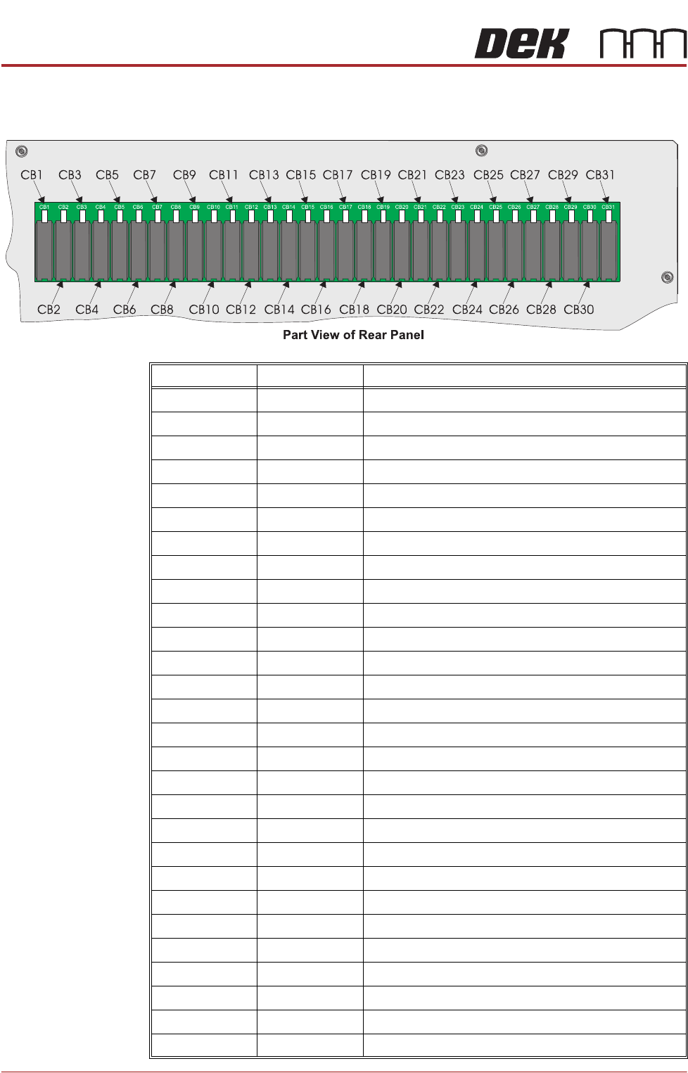
Circuit Breakers
CCT Breaker Current Rating CCT Breaker Function
CB1 3.15A +24V US Fans, E Stop Relay, 2 Handed Safety Relay
CB2 3.15A +5.5V USB Hub (Spare)
CB3 1.5A -12V NextMove ES
CB4 3.15A +5.5V NextMove ES
CB5 1.5A +24V US NextMove I/F, MIU, Camera Lighting
CB6 1.5A +24V SW NextMove I/F, MIU, System Lamp
CB7 1.5A +12V
CB8 3.15A +24V SW Belt Motors
CB9 3.15A +24V US EuroFlex, Stepper Logic, Fans
CB10 6.3A +24V SW Steppers
CB11 3.15A +24V US Main Machine I/O Node (Node 2)
CB12 3.15A +24V SW Main Machine I/O Node (Node 2)
CB13 1.5A +12V I/O Nodes (Nodes 2-4), M40 Dual Lane Controller
CB14 3.15A +24V US Print Carriage I/O Node (Node 3)
CB15 3.15A +24V SW Print Carriage I/O Node (Node 3)
CB16 3.15A +24V US Screen Cleaner I/O Node (Node 4)
CB17 3.15A +24V SW Screen Cleaner I/O Node (Node 4)
CB18 3.15A +24V US M40 Dual Lane Controller
CB19 3.15A +24V SW
CB20 3.15A +24V US Paste Dispenser I/O Node
CB21 3.15A +24V SW Paste Dispenser I/O Node
CB22 1.5A +12V Paste Dispenser I/O Node
CB23 3.15A +24V US HTC Enclosure
CB24 3.15A +24V SW HTC Enclosure
CB25 3.15A +24V US Grid-Lok
CB26 3.15A +24V SW Grid-Lok
CB27 3.15A +24V US Internal Lighting
CB28 3.15A +24V SW Spare I/O Node