Micron Technical Reference V9 Volume 1.pdf - 第13页
INTRODUCTION MANUAL STRUCTURE Chapter Issue 12, Feb 18 Technical Reference Manual 1.3 MANUAL STRUCTURE The T echnical Reference Manual is composed around four defined areas: • Manual Introduction and Overview • Printer E…

INTRODUCTION
DOCUMENTATION
1.2 Technical Reference Manual Chapter Issue 12, Feb 18
Electronic
DVD The following information is provided on DVD:
• Instruction Guide (in all available languages)
• Installation Manual
• Technical Reference Manual
• Operator Manual (in all available languages)
• Electrical Drawings
• Machine Tutorials
• Consumable Replenishment Tutorials
Hard Disk The following information is provided on the printer PC hard disk:
• Instruction Guide (in all available languages)
• Installation Manual
• Technical Reference Manual
• Operator Manual (in all available languages)
• Printer Tutorials
• Consumable Replenishment Tutorials
Hard Copy The following documentation is included in hard copy format with the printer:
• Instruction Guide (in all available languages)
• Installation Manual
• Operator Manual (in language specified by customer)
• Electrical Drawings (A3 format)
INTRODUCTION
MANUAL STRUCTURE
Chapter Issue 12, Feb 18 Technical Reference Manual 1.3
MANUAL STRUCTURE
The Technical Reference Manual is composed around four defined areas:
• Manual Introduction and Overview
• Printer Electrical and Electronics Areas
• Printer Modules
• Miscellaneous Information
Based upon the areas above, the manual is divided into chapters. A listing of
all chapters is detailed in the contents pages of this manual.
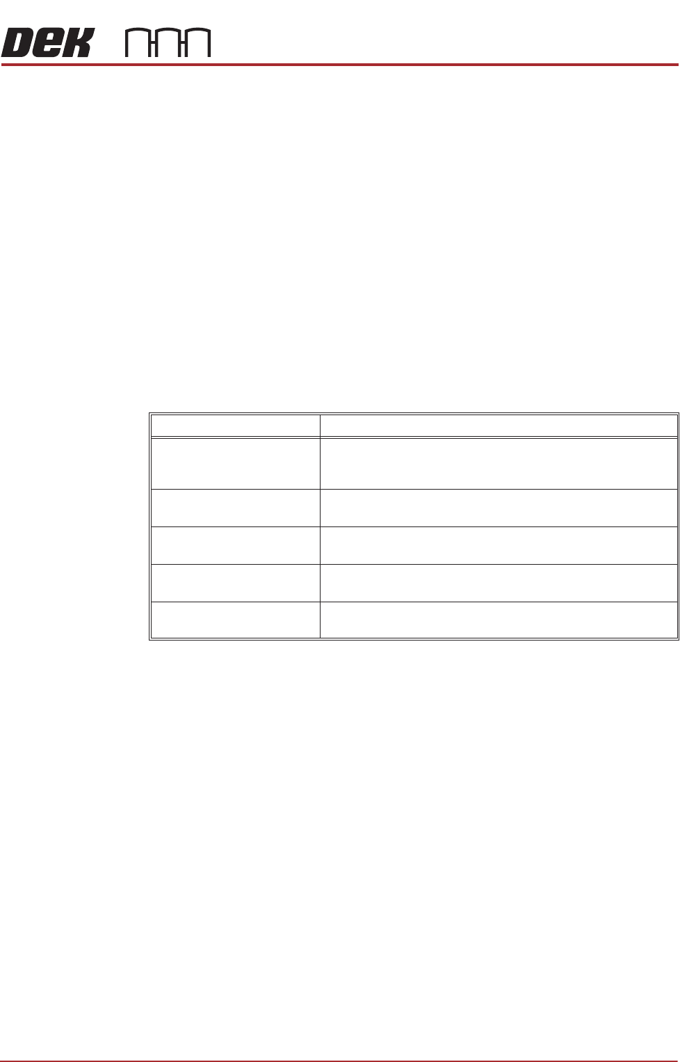
Chapter Structure The structure of each chapter within the manual may vary dependent upon
layout of information, (with the exception of module chapters).
All printer module chapters are given a common generic structure, enabling the
user to become familiarized with a standard module information layout. The
breakdown of a typical module chapter is detailed in the table below:
Section Heading Description
Overview Includes a diagrammatic overview with a description of the
module operation, detailing relevant sequences and/or posi-
tional information.
Pneumatic and/or Electrical
Schematic
Block diagram detailing the electrical system, including signals,
electronic components etc, (and pneumatics if necessary).
Adjustments and Settings Provides information on any adjustment and/or setting in order
to enable correct module functionality.
Replacement Procedures Where applicable, details technical instruction for the replace-
ment of individual components within the module.
Calibrations Where applicable, describes how to calibrate the module follow-
ing installation, adjustment or replacement procedures.
INTRODUCTION
CONVENTIONS
1.4 Technical Reference Manual Chapter Issue 12, Feb 18
CONVENTIONS
General The manual follows a logical method of portraying information to the user. This
philosophy is consistent across the complete range of manuals.
The following briefly describes the conventions typical of any DEK technical
publication.
Page Layout An example of a typical chapter page layout is detailed in the Typical Page
Layout figure.
Safety Notices Safety notices and associated symbols are utilized throughout the complete
manual range to highlight to the user the possible risks that may cause injury to
personnel (for further information refer to the Safety Features Chapter). An
example is shown below:
WARNING
BOARD CLAMPS. EXTREME CARE MUST BE EXERCISED WHEN WORKING IN
THE TOOLING AREA OF THE MACHINE TO AVOID INJURY. THE FOILS ON THE
FRONT AND REAR BOARD CLAMPS ARE VERY SHARP.
Notes Notes are used extensively throughout the manuals both in text and graphics to
provide additional information to the user. Notes are displayed in italic text
prefixed by the word in uppercase. An example is shown below:
NOTE
Detailed information regarding print processing in general is highlighted......
Bold Text Bold text is used throughout the manuals to identify the following occurrences:
• An action on the user, (example shown below):
1. Select Run Diagnost.
• A message displayed on the monitor screen, (example shown below):
The following message is displayed: ‘Ensure that the correct squeegees are
fitted.’
• A dimension, (example shown below):
1. Loosen the securing screw using a 4mm Allen key.