Micron Technical Reference V9 Volume 1.pdf - 第136页
POWER SUPPLY M37 M37 POWER SUPPLY ENCLOSURE 5.22 Technical Reference Manual Chapter Issue 13, Jan 17
POWER SUPPLY M37
M37 POWER SUPPLY ENCLOSURE
Chapter Issue 13, Jan 17 Technical Reference Manual 5.21
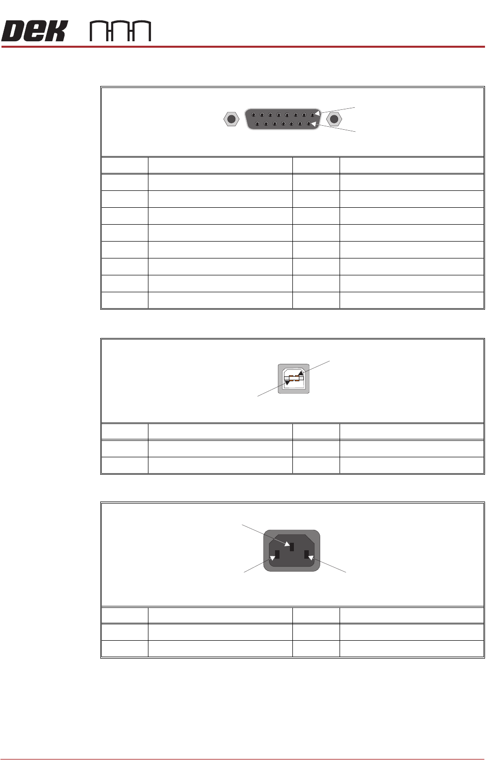
M37SK27
M37SK30
M37SK31 to M37SK35
Pin No. Signal Pin No. Signal
1 System Button 9 Right Jog Button
2 System Button 10 Right Jog Button
3 System Lamp 11 Right Jog Button
4 System Lamp 12 Right Jog Button
5 Left Jog Button 13 RSVD (Cat 4)
6 Left Jog Button 14 RSVD (Cat 4)
7 Left Jog Button 15 N/C
8 Left Jog Button
15 Way D Type Socket
9
1
Pin No. Signal Pin No. Signal
1 USB Supply 3 USB Data +ve
2 USB Data -ve 4 USB Ground
Pin No. Signal Pin No. Signal
1Live 3Earth
2Neutral
1
4
USB Type B Socket
1
2
AC
Mains
Socket
3

POWER SUPPLY M37
M37 POWER SUPPLY ENCLOSURE
5.22 Technical Reference Manual Chapter Issue 13, Jan 17
MACHINE PC H81
OVERVIEW
Chapter Issue 3, Feb 18 Technical Reference Manual 6.1
CHAPTER 6 MACHINE PC H81
OVERVIEW
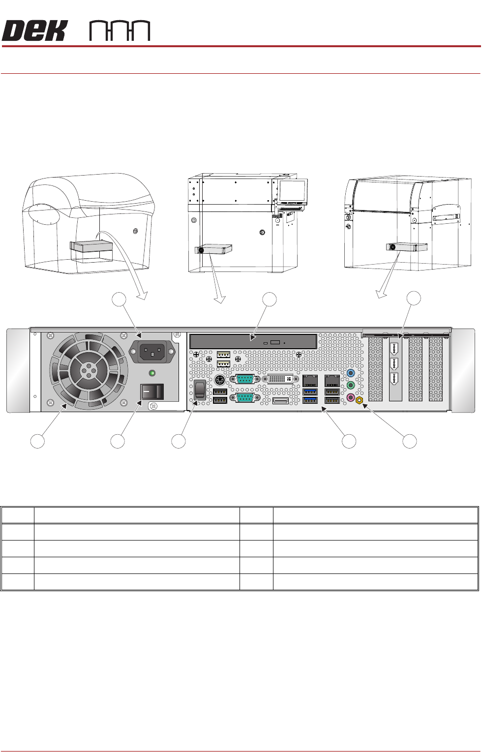
Figure 6-1 Electronic Assembly (EA) Machine
The machine PC handles all the machine functions (via CAN Bus and LAN Host
Comms), printer cameras and the MMI.
The PC for the Electronic Assembly machine is configured using a dual core
processor with standard PCI for the camera system.
0
PC Enclosure PanelConnector
2
3
4
6
5
7
8
1
Item Description Item Description
1 PCI Interface Card 5 Mains Power On/Off Switch
2 Earth Bonding Connector 6 Cooling Fan
3 Peripheral Connector Panel 7 Mains Input Connector
4 Reset Switch 8 DVD ROM Drive