Micron Technical Reference V9 Volume 1.pdf - 第144页
MACHINE PC H81 PERIPHERAL DEVICES 6.8 Technical Reference Manual Chapter Issue 3, Feb 18 PERIPHERAL DEVICES DVD ROM Drive The 5.25 inch DVD ROM Drive is located at the top front of the enclosure and is used for installin…
MACHINE PC H81
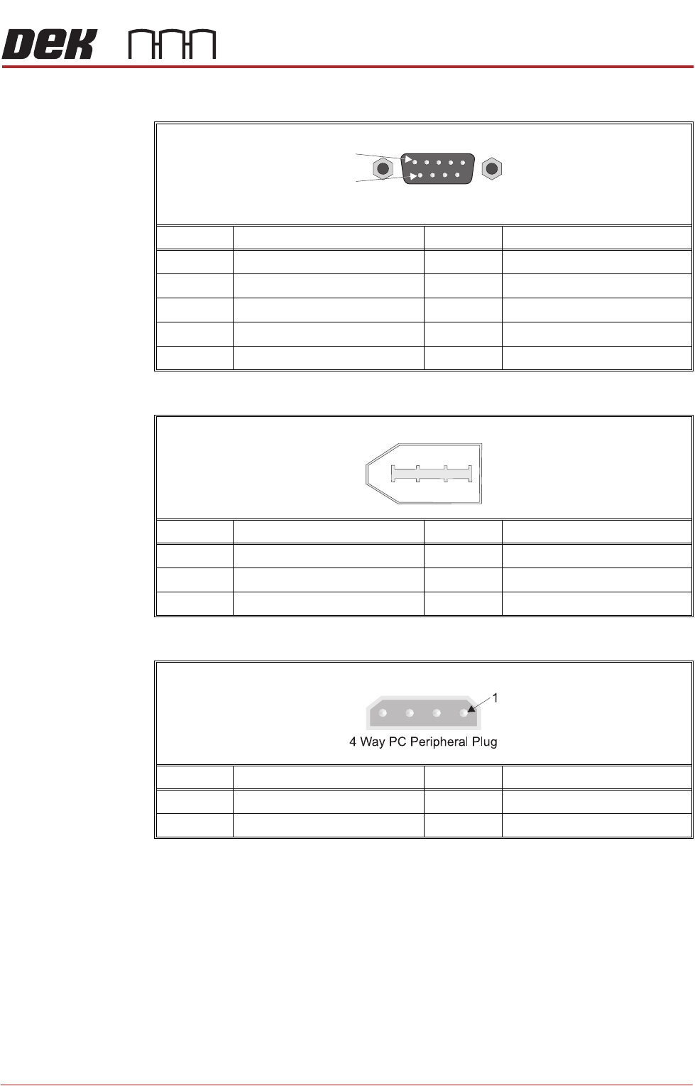
FRONT PANEL CONNECTORS
Chapter Issue 3, Feb 18 Technical Reference Manual 6.7
COM 1 RS232
1394a PCI Interface Card (Port 1 - 3)
1394a PCI Interface Card Power Connector
Pin No.SignalPin No.Signal
1 Data Carrier Detect (DCD) 6 Data Set Ready (DSR)
2 Receive Data (RxD) 7 Request To Send (RTS)
3 Transmit Data (TxD) 8 Clear To Send (CTS)
4 Data Terminal Ready (DTR) 9 Ring Indicator (RI)
5 Signal Ground (GND)
Pin No.SignalPin No.Signal
1 Power 6 Twisted Pair B+
2 Ground 7 Twisted Pair A-
3 Twisted Pair B- 8 Twisted Pair A+
Pin No.SignalPin No.Signal
1 Power (+12V) 3 Ground
2 Ground 4 Power (+5V)
9 Way D Type Plug
1
6
1
5
2
6
3
4

MACHINE PC H81
PERIPHERAL DEVICES
6.8 Technical Reference Manual Chapter Issue 3, Feb 18
PERIPHERAL DEVICES
DVD ROM Drive The 5.25 inch DVD ROM Drive is located at the top front of the enclosure and
is used for installing machine software.
MACHINE CONTROL
OVERVIEW
Chapter Issue 12, Feb 18 Technical Reference Manual 7.1
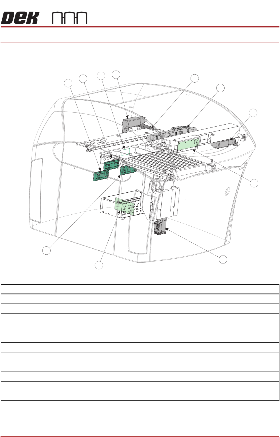
CHAPTER 7 MACHINE CONTROL
OVERVIEW
NOTE
Node boards 1, 2, 4, 5 and servo node 9 are positioned and accessed from the
front of Type 4 machines
Item Node Description
1 Servo Node 8 Camera X Motor (Rotary Servo Drive Only)
2 Stepper Node 10 Paste Dispenser Motor
3 Servo Node 7 Print Carriage Motor
4 I/O Node Board 3 (behind panel) Print Carriage I/O
5 Servo Node 6 Rising Table Motor
6 I/O Node Board 1 (NextMove ES) Inside Machine Control Enclosure
7 I/O Node Board 4 (with fabric feed brake module) Screen Cleaner I/O
8 I/O Node Board 2 Main Machine I/O
9 I/0 Node Board 5 Shared functionality OTS and HTC
10 I/O Node 18 Proactiv Interface
11 Servo Node 9 Camera Y Motor (Rotary Servo Drive Only)
1
2
3
4
5
6
7
8
11
10
9