Micron Technical Reference V9 Volume 1.pdf - 第150页
MACHINE CONTROL M36 MACHINE CONTROL ENCLOSURE 7.6 Technical Reference Manual C hapter Issue 12, Feb 18 There are four surface mount LEDs on the board which are detaile d in the table below , NextMove ES Card figure refer…
MACHINE CONTROL
M36 MACHINE CONTROL ENCLOSURE
Chapter Issue 12, Feb 18 Technical Reference Manual 7.5
NextMove ES Card
CAUTION
ANTI-STATIC HANDLING. STANDARD PRECAUTIONS MUST BE ADHERED TO
WHEN HANDLING ELECTRONIC CARDS AND CONFIGURING AND INSERTING
INTO THE ENCLOSURES.
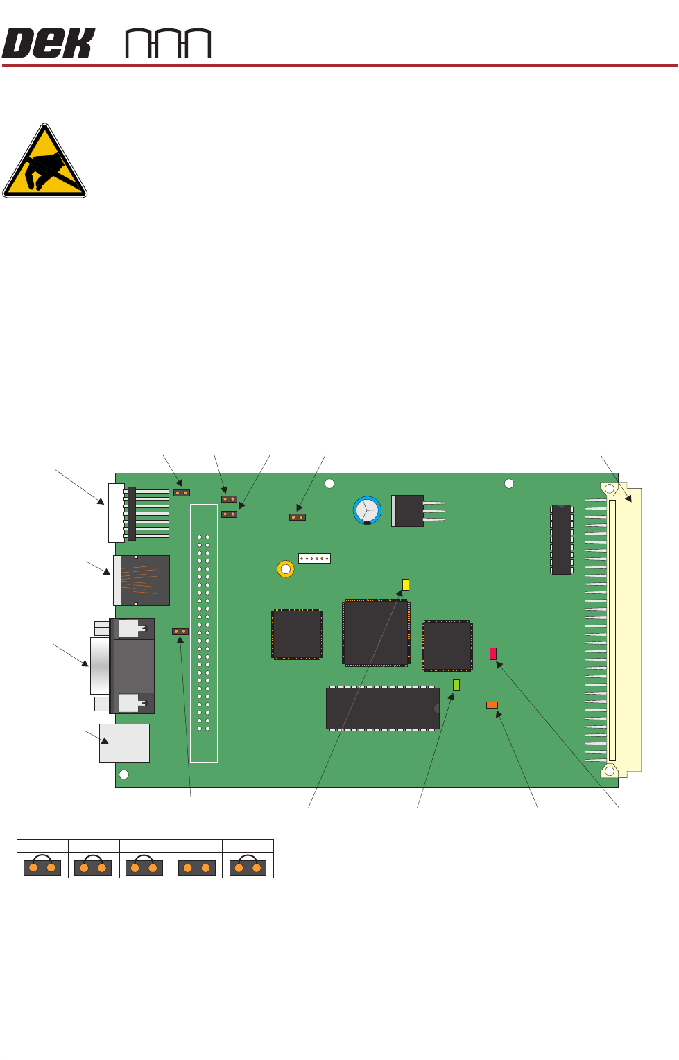
The NextMove ES can control six stepper motor axes via stepper drive cards
and provides 4 analogue outputs, 2 analogue inputs, 20 digital inputs (interfaced
through the NextMove Interface card) and 8 digital outputs (interfaced through
the NextMove Interface card). Two of the analogue outputs are used as demand
outputs to control linear motors for camera X and Camera Y (linear drive
machines only). The card also incorporates a CAN encoder/decoder which
connects to I/O Node boards and Servo/Stepper Nodes using a CAN Bus
network. The CAN Bus network allows for future expansion of the system
without the need for further NextMove cards.
NextMove ES
Jumper Settings
The NextMove ES jumper settings are shown below:
Figure 7-2 NextMove ES Card
LED Indications The 7 segment LED display on the edge of the NextMove ES card indicates the
Node number (1) during normal operation. During initialisation, the display
indicates a dash (-) followed by a period (.).
JP1
JP2
JP3 JP4 JP57 Segment
LED Display
CAN Bus
Connector
M36SK35
Not Used
USB
Connector
M36SK28
96 Pin Edge Connector
JP3
JP2
JP1
JP4
JP5
D3
D4
D16
D20
MACHINE CONTROL
M36 MACHINE CONTROL ENCLOSURE
7.6 Technical Reference Manual Chapter Issue 12, Feb 18
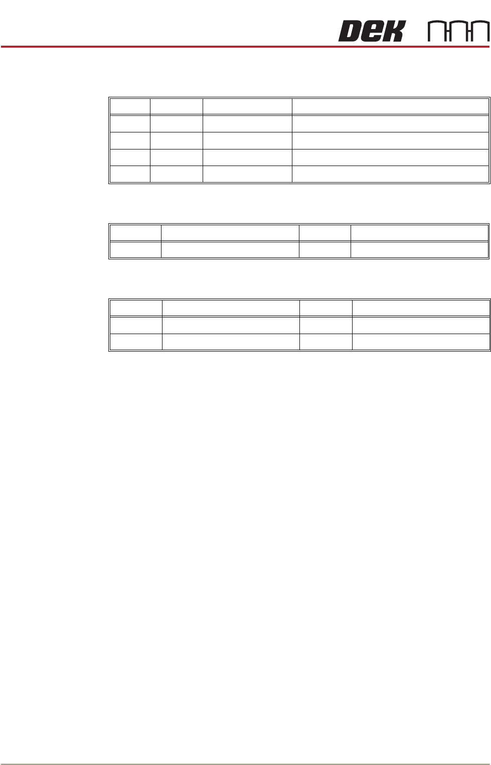
There are four surface mount LEDs on the board which are detailed in the table
below, NextMove ES Card figure refers:
Inputs The table below details the 2 analogue inputs:
Outputs The table below details the 4 analogue outputs:
LED Colour Normal Operation Purpose
D3 Yellow Off Indicates that the FPGA is being initialised
D4 Red Off Indicates that the card is in hardware reset
D16 Green Flashing Flashes at 0.5Hz to indicate firmware heartbeat
D20 Orange On Toggles on with reception of comms packet
Input Function Input Function
AIN0 USC Solvent Level AIN1 Spare
Output Function Output Function
AOUT0 Camera X (linear drive only) AOUT2 Spare
AOUT1 Camera Y (linear drive only) AOUT3 Temperature Output to TCM
MACHINE CONTROL
M36 MACHINE CONTROL ENCLOSURE
Chapter Issue 12, Feb 18 Technical Reference Manual 7.7
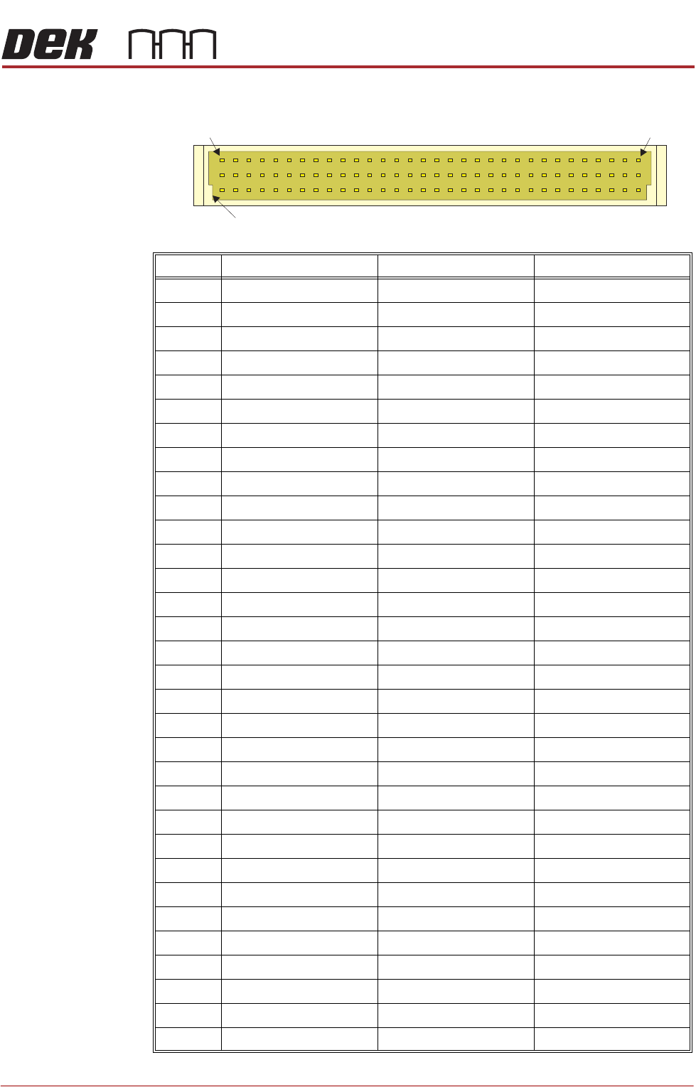
NextMove ES Edge
Connector
The edge connector connects the card to the backplane of the enclosure.
Pin No. Row a Row b Row c
1 +5.5V +5.5V +5.5V
2 +5.5V +5.5V +5.5V
3 DGND DGND DGND
4 OUT COM DOUT7 DOUT6
5 DOUT5 DOUT4 DOUT3
6 DOUT2 DOUT1 DOUT0
7 Encoder 0 CHB Encoder 0 CHA Encoder 1 CHB
8 Encoder 1 CHA Encoder 0 Index Encoder 1 Index
9 Encoder 1!Index Encoder 0!Index Encoder 1!CHA
10 Encoder 1!CHB Encoder 0!CHA Encoder 0!CHB
11 DGND Error Out DIN16
12 DGND DGND !RST IN
13 STEP4 DIR4 DGND
14 STEP0 STEP1 STEP2
15 DIR0 DIR1 DIR2
16 RSVD DGND STEP5
17 RSVD AOUT2 DGND
18 DIN2 DIN15 DIN4
19 DIN7 DIN5 DIN3
20 RXD DIN1 DIN6
21 TXD RTS DIN0
22 CTS AOUT3 DIR5
23 DIR3 STEP3 DIN14
24 DIN10 DIN13 DIN17
25 DIN11 DIN9 DIN18
26 DIN8 DIN19 DIN12
27 AIN1- Demand1 (AOUT1) Demand0 (AOUT0)
28 AIN0- AIN0+ AIN1+
29 +12V DC +12V DC +12V DC
30 AGND AGND AGND
31 -12V DC -12V DC -12V DC
32 Shield Shield Shield
a
b
c
1 32
Keyway