Micron Technical Reference V9 Volume 1.pdf - 第158页
MACHINE CONTROL M36 MACHINE CONTROL ENCLOSURE 7.14 Technical Reference Manual C hapter Issue 12, Feb 18 Stepper Drive Card Edge Connector The edge connector conn ects the card to the backplane of the enclosure. Pin No. R…
MACHINE CONTROL
M36 MACHINE CONTROL ENCLOSURE
Chapter Issue 12, Feb 18 Technical Reference Manual 7.13
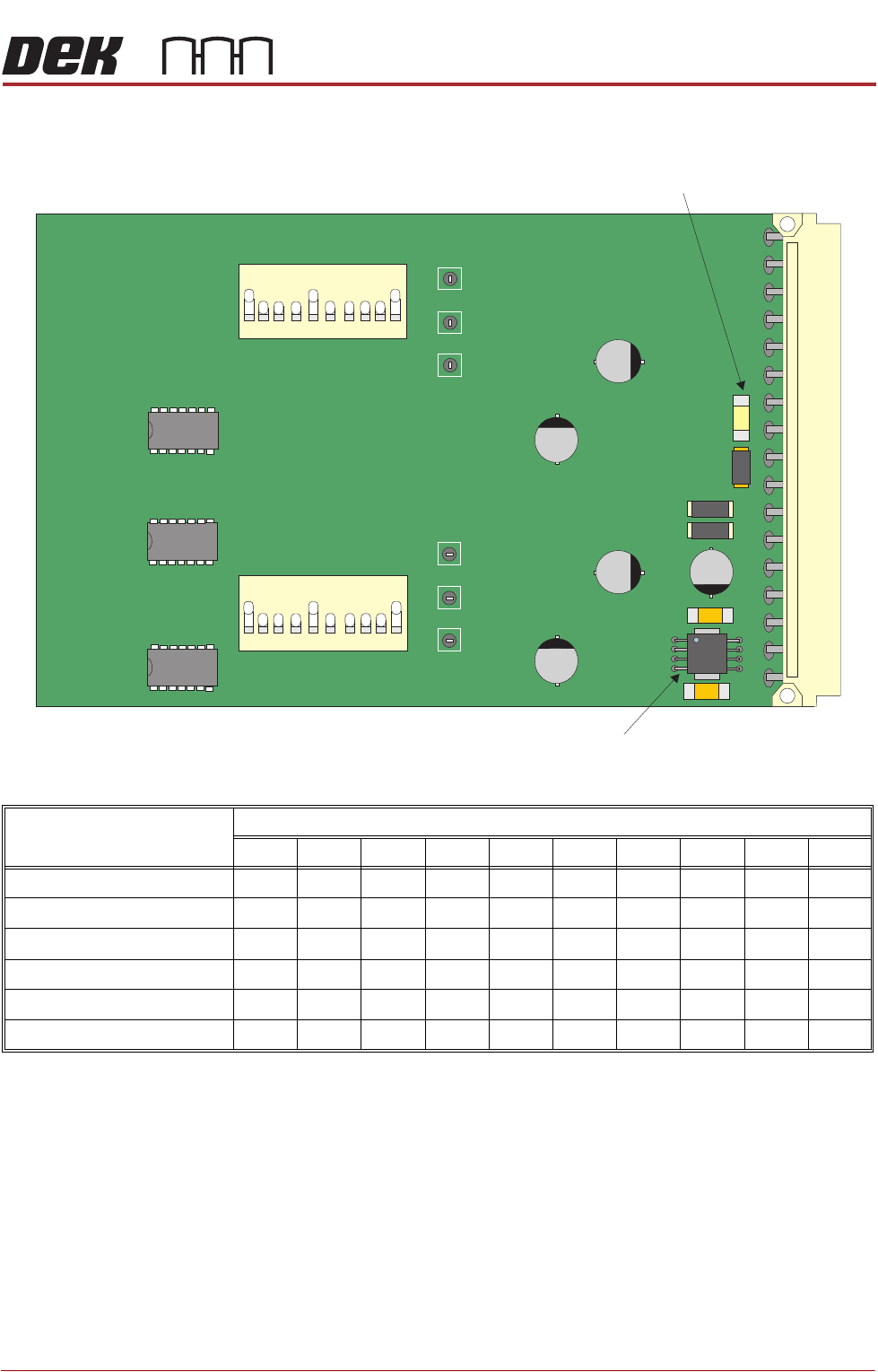
Dipswitch Settings Use the following graphic and tables to determine the correct dipswitch settings:
Figure 7-4 Dual Stepper Drive Card
Card Position and Dipswitch Switch Positions
12345678910
Slot X1 - SW 1 OFF ON ON ON ON OFF ON OFF ON OFF
Slot X1 - SW 2 OFF ON ON ON ON OFF ON OFF ON OFF
Slot X2 - SW 1 OFF ON ON ON ON OFF ON ON ON OFF
Slot X2 - SW 2 OFF ON ON ON ON OFF ON ON ON OFF
Slot X3 - SW 1 OFF ON ON ON ON OFF ON OFF ON OFF
Slot X3 - SW 2 OFF ON ON ON ON OFF ON ON ON OFF
SW1
SW2
12
3
4
56
7
8
9
10
ON
12
3
4
56
7
8
9
10
ON
5V Regulator
Fuse F1
MACHINE CONTROL
M36 MACHINE CONTROL ENCLOSURE
7.14 Technical Reference Manual Chapter Issue 12, Feb 18
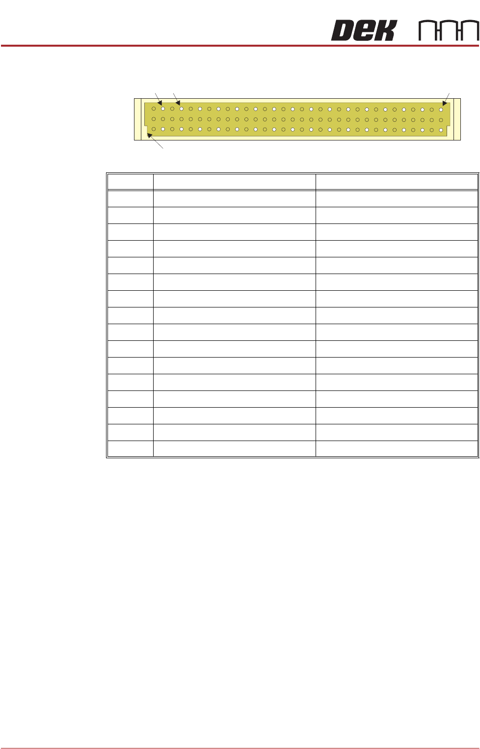
Stepper Drive Card
Edge Connector
The edge connector connects the card to the backplane of the enclosure.
Pin No. Row a Row c
2 CH1 B- CH2 B-
4 CH1 B+ CH2 B+
6 CH1 A- CH2 A-
8 CH1 A+ CH2 A+
10 24V SW 24V SW
12 24V US 24V SW
14 24V US 24V SW
16 GND GND
18 GND GND
20 N/C N/C
22 N/C N/C
24 IDAT ICLK
26 IVPP DIR1
28 VCC OUT STEP1
30 DIR2 STEP2
32 N/C N/C
a
c
2 32
Keyway
4
MACHINE CONTROL
M36 MACHINE CONTROL ENCLOSURE
Chapter Issue 12, Feb 18 Technical Reference Manual 7.15
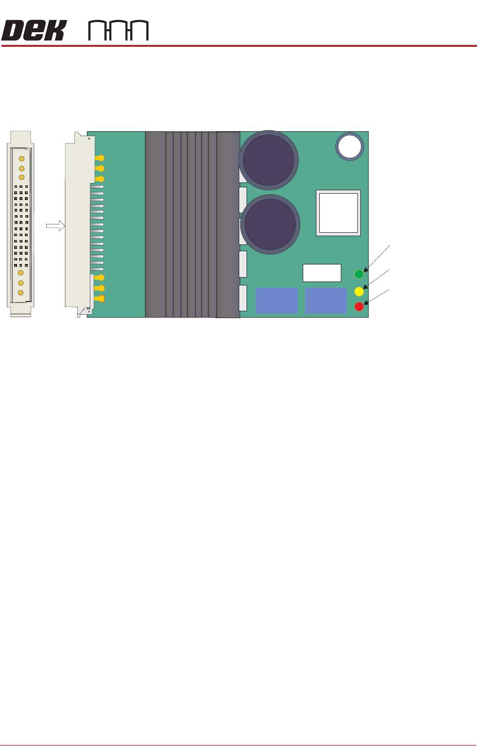
Servo Drive Card On linear drive machines only, two servo drive cards are used by the machine
controller to drive the camera X and Y axis motors. The axes for these motors
are designated Axis 0 and 1.
Figure 7-5 Servo Drive Card Layout (for linear motors)
A
View on A
C1 B1 A1
Card Error
(includes system
power off)
Card Disabled
(by software control)
Card Powered
(no errors)