Micron Technical Reference V9 Volume 1.pdf - 第216页
MACHINE CONTROL SIGNALS BREAKOUT CONNECTOR 7.72 Technical Reference Manual C hapter Issue 12, Feb 18
MACHINE CONTROL
SIGNALS BREAKOUT CONNECTOR
Chapter Issue 12, Feb 18 Technical Reference Manual 7.71
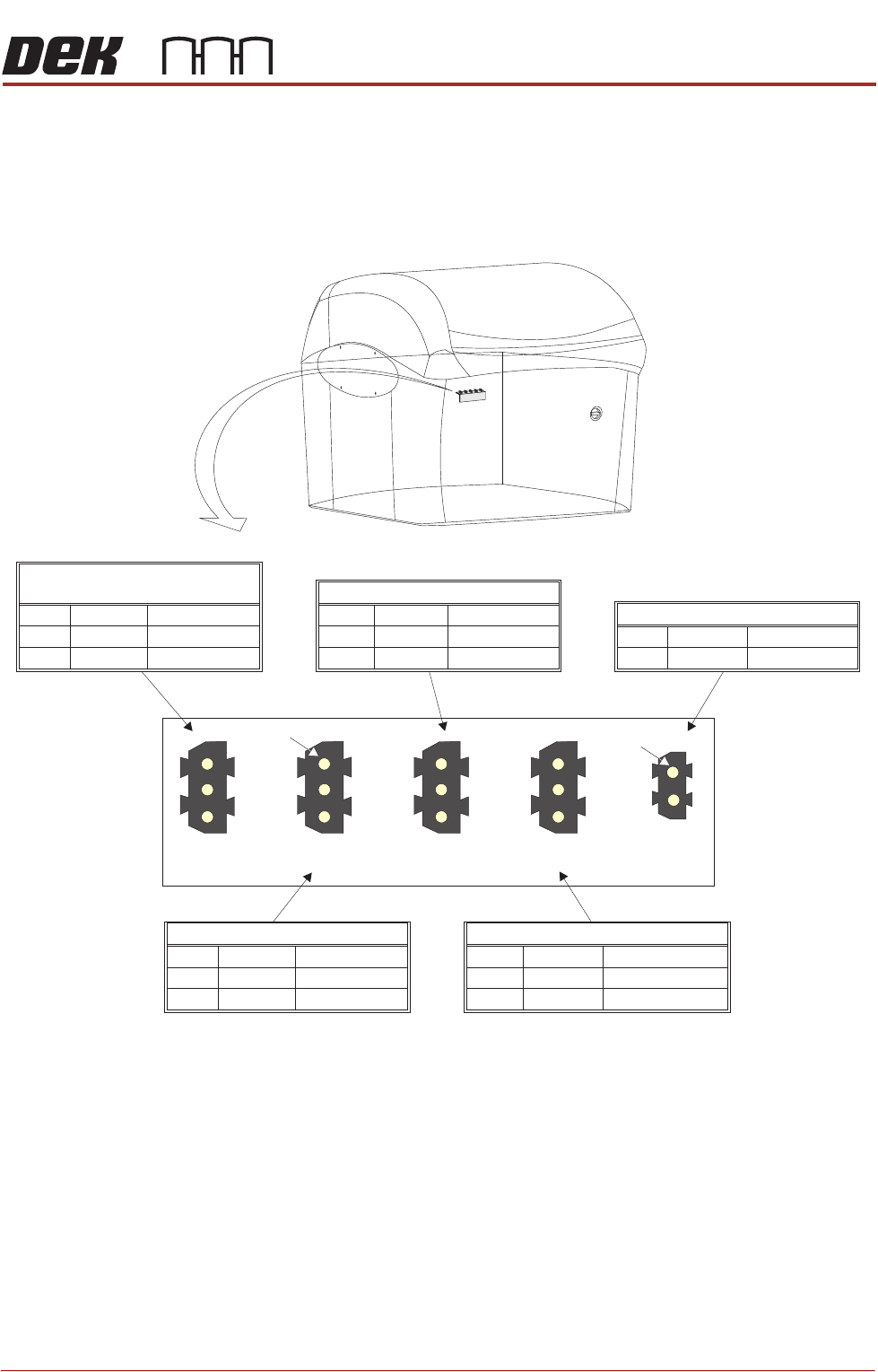
SIGNALS BREAKOUT CONNECTOR
Mounted on the rear frame of the machine, the signals breakout connectors are
extensions of some of the I/Os from the NextMove Interface card. The Spare
Output and Inputs are available for machine options.
Pin 1
Pin 2
Pin 3
+12V
DIG IN 19
0V
Rail Clash Sensor
(Dual Lane machine only)
Wire 001
Wire 021
Wire 180
12VWire 021
Pin 1
Pin 2
Pin 3
DIG IN 5
0V
Moving Rail Home
Wire 166
Wire 001
Pin 1
Pin 2
Pin 3
+12V
DIG IN 0
0V
Spare Input
Wire 161
Wire 021
Wire 001
Pin 1
Pin 2
Pin 3
+12V
DIG IN 2
0V
Camera Y Home (linear motors)
Wire 021
Wire 163
Wire 001
8SK24 8SK25 8SK26 8SK27
8SK28
Pin 1
Pin 2
DIG OUT 4
0V Return
HTC Enable/Spare Output
Wire 185
Wire 050
Pin 1
Pin 1

MACHINE CONTROL
SIGNALS BREAKOUT CONNECTOR
7.72 Technical Reference Manual Chapter Issue 12, Feb 18
PRINT CARRIAGE MODULE
OVERVIEW
Chapter Issue 5, Aug 14 Technical Reference Manual 8.1
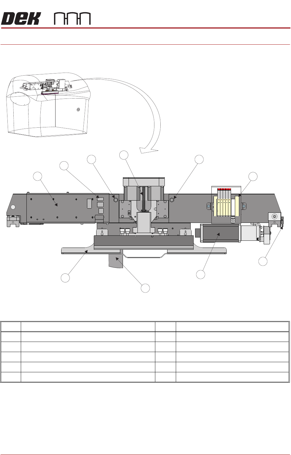
CHAPTER 8 PRINT CARRIAGE MODULE
OVERVIEW
Item Description Item Description
1 Print Carriage Solenoids (Cover Shown Transparent) 6 I/O Node Board 3 (Behind Panel)
2 Print Carriage Home Sensor 7 Printhead Mechanism Connector Panel
3 Print Carriage Servo Motor 8 ProFlow Pneumatic Connectors (2 Positions)
4 Screen Loader Mechanism 9 Squeegee Printhead Mechanism
5 Squeegee Drip Tray
Print Carriage Front View (Squeegee Mechanism Fitted)
1
2
4
5
6
7
8
9
8
3