Micron Technical Reference V9 Volume 1.pdf - 第223页
PRINT CARRIAGE MODULE ADJUSTMENTS AND SETTINGS Chapter Issue 5, Aug 14 Technical Reference Manual 8.7 17. G ain access to the print carriage home sensor van e on the right hand printhead. 18. Adjust the position of the h…
PRINT CARRIAGE MODULE
ADJUSTMENTS AND SETTINGS
8.6 Technical Reference Manual Chapter Issue 5, Aug 14
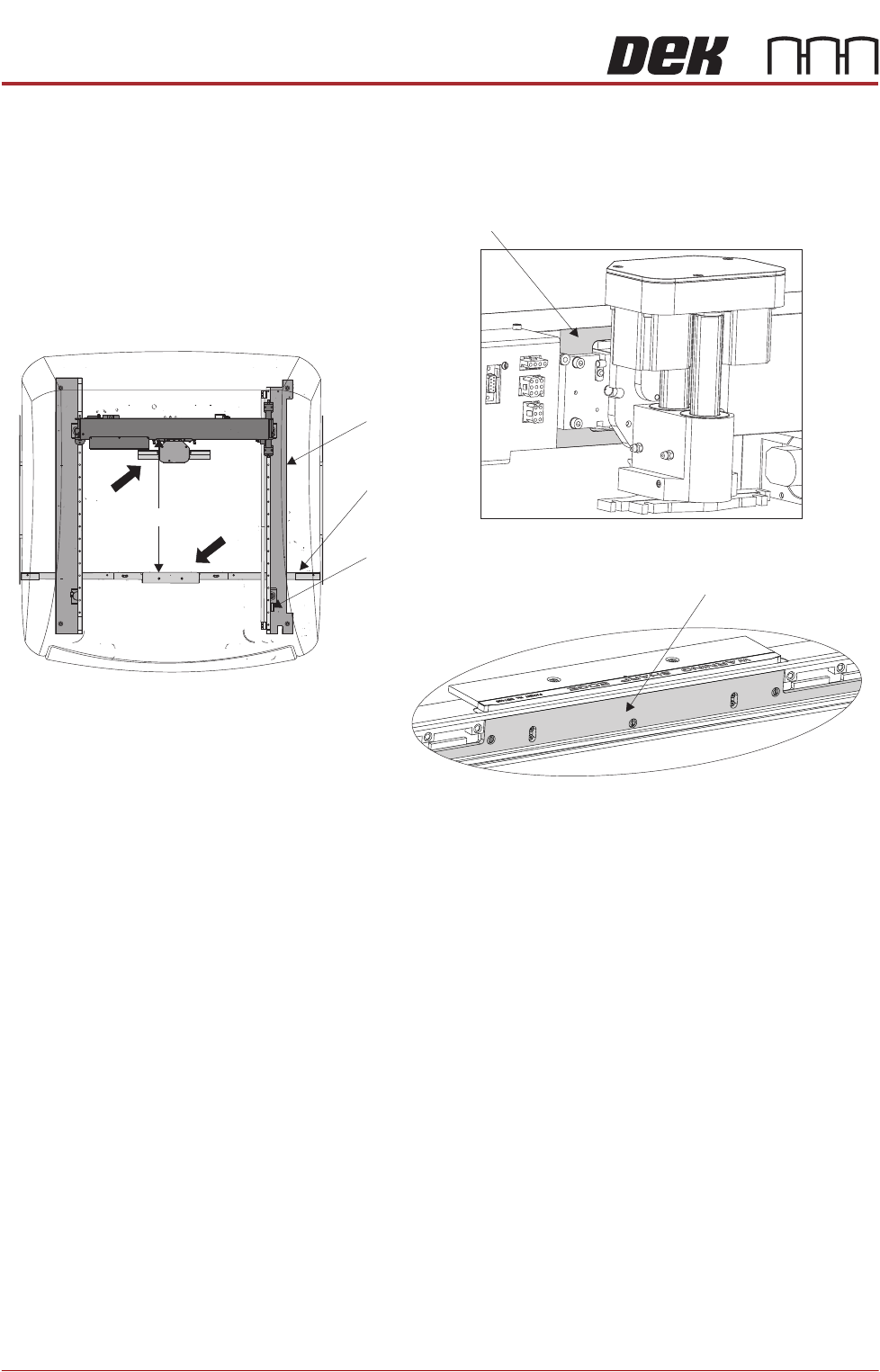
15. Measure the horizontal distance between the inside face of the front rail belt
support plate and the print carriage machined face, (squeegee/ProFlow
interface area), the correct setting being 612.0mm +/- 2.0mm.
16. If the adjustment is correct go to Step 22.
Front Rail
Machine Plan View
Print Carriage Machined Face
Home Sensor
Vane
Right Hand
Printhead
View on Arrow A
View on Arrow B
Belt Support Plate
612mm +/- 2.0mm612mm +/- 2.0mm
A
B
PRINT CARRIAGE MODULE
ADJUSTMENTS AND SETTINGS
Chapter Issue 5, Aug 14 Technical Reference Manual 8.7
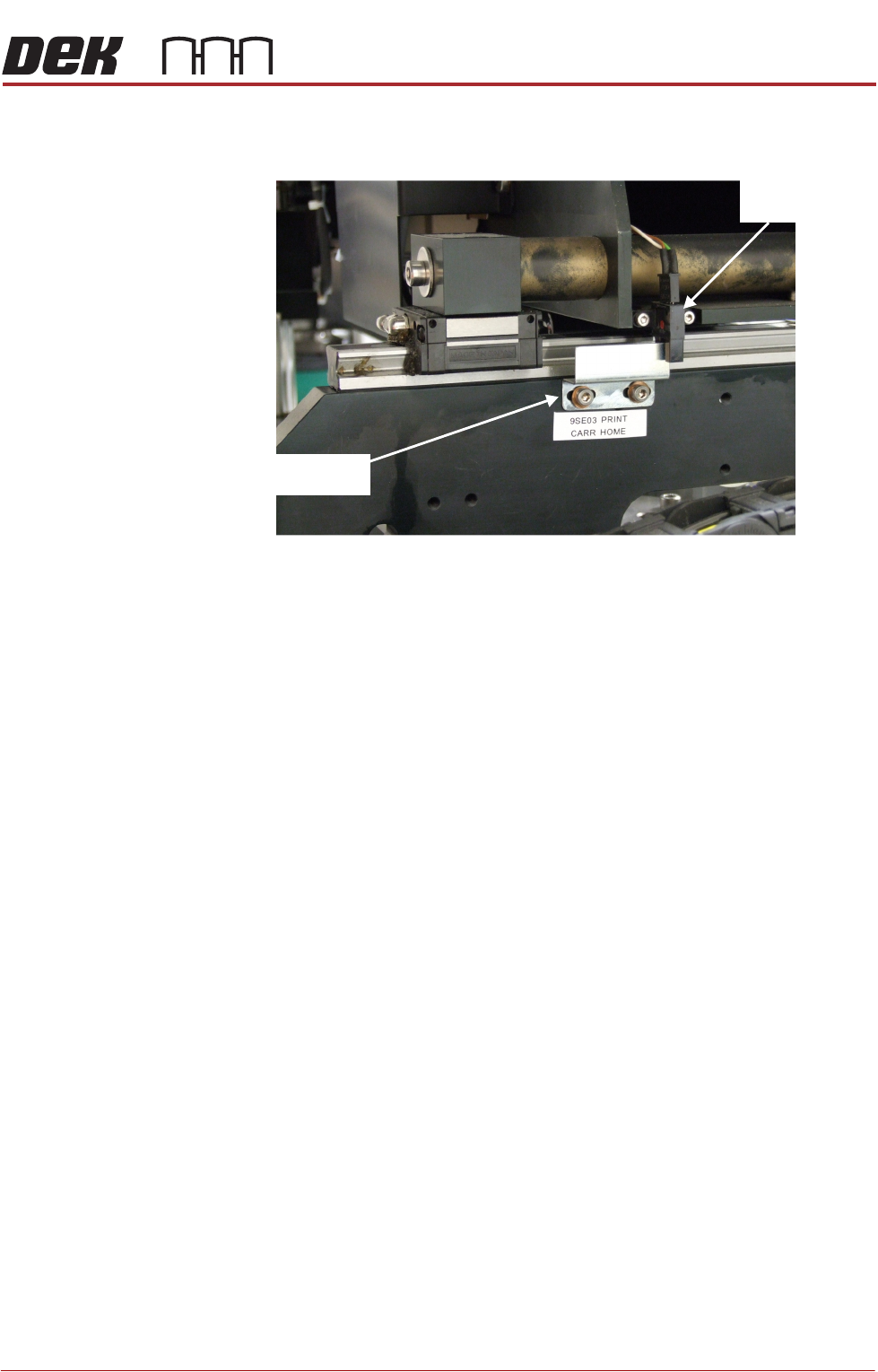
17. Gain access to the print carriage home sensor vane on the right hand
printhead.
18. Adjust the position of the home sensor vane.
19. Close the front printhead cover.
20. Press the System button.
21. Repeat Steps 10 to 16 until this measurement is achieved.
22. Refit the stencil.
23. Close the front printhead cover.
24. Press the System button.
25. Select Exit.
26. Select Exit.
27. Select Back.
Print Carriage
Home Sensor
Print Carriage
Home Sensor Vane
View On Right Hand Printhead
PRINT CARRIAGE MODULE
REPLACEMENT PROCEDURES
8.8 Technical Reference Manual Chapter Issue 5, Aug 14
REPLACEMENT PROCEDURES
Timing Belt To replace the print carriage timing belt, carry out the following procedure:
NOTE
Type 4 machines need to be moved out of line to perform this procedure. Refer
to Machine Preparation in the installation manual.
1. Select Open Cover Commands.
2. Select Carriage to Front.
3. Select Back.
4. Select Shut Down.
5. Select Continue.
6. Switch the mains isolator to OFF.
7. Gain access to the right hand printhead.
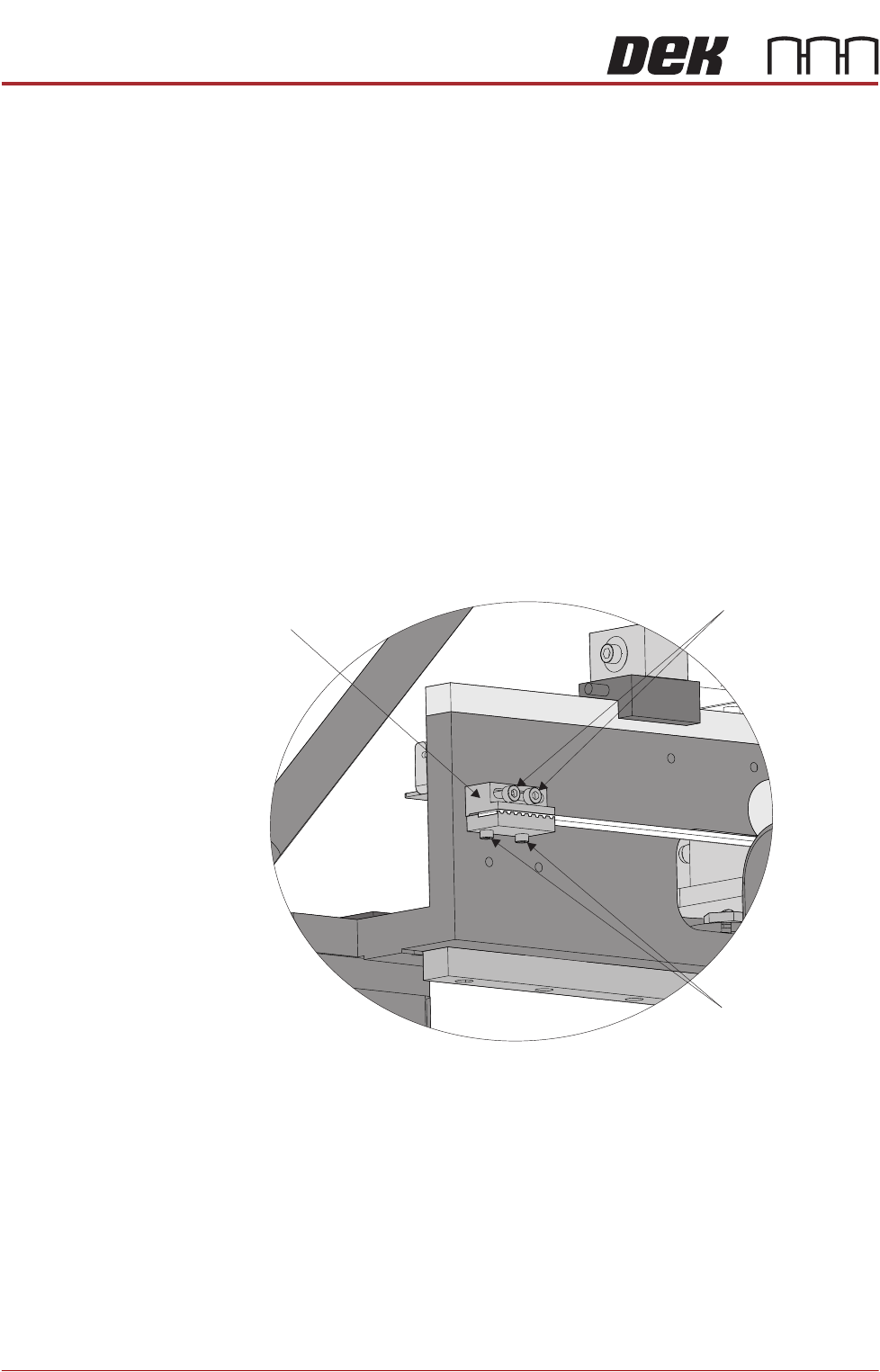
8. Locate the rear print carriage timing belt clamp on the inner face of the right
hand printhead. Loosen the two belt securing screws and remove the belt
end from the clamp.
9. Unthread the timing belt from print carriage motor pulley and idle pulleys.
10. Locate the front print carriage timing belt clamp on the inner face of the right
hand printhead. Loosen the two belt securing screws, remove and discard
the timing belt.
11. Fit the replacement timing belt into the front belt clamp and tighten the
securing screws sufficiently to hold the belt.
12. Thread the timing belt under the front print carriage idle pulley, over the print
Print Carriage
Timing Belt Clamp
Belt Clamp
Adjustment Screws
Belt Securing
Screws
View on Rear of Right Hand Printhead