Micron Technical Reference V9 Volume 1.pdf - 第229页
SQUEEGEE MODULE OVERVIEW Chapter Issue 6, Jul 16 Technical Reference Manual 9.1 CHAPTER 9 SQUEEGEE MODULE OVER VIEW Item Description Item Description 1 Squeegee Prin thead Mechanism 5 Squeegee Drip T ray 2 Rear Squeegee …

PRINT CARRIAGE MODULE
CALIBRATIONS
8.12 Technical Reference Manual Chapter Issue 5, Aug 14
SQUEEGEE MODULE
OVERVIEW
Chapter Issue 6, Jul 16 Technical Reference Manual 9.1
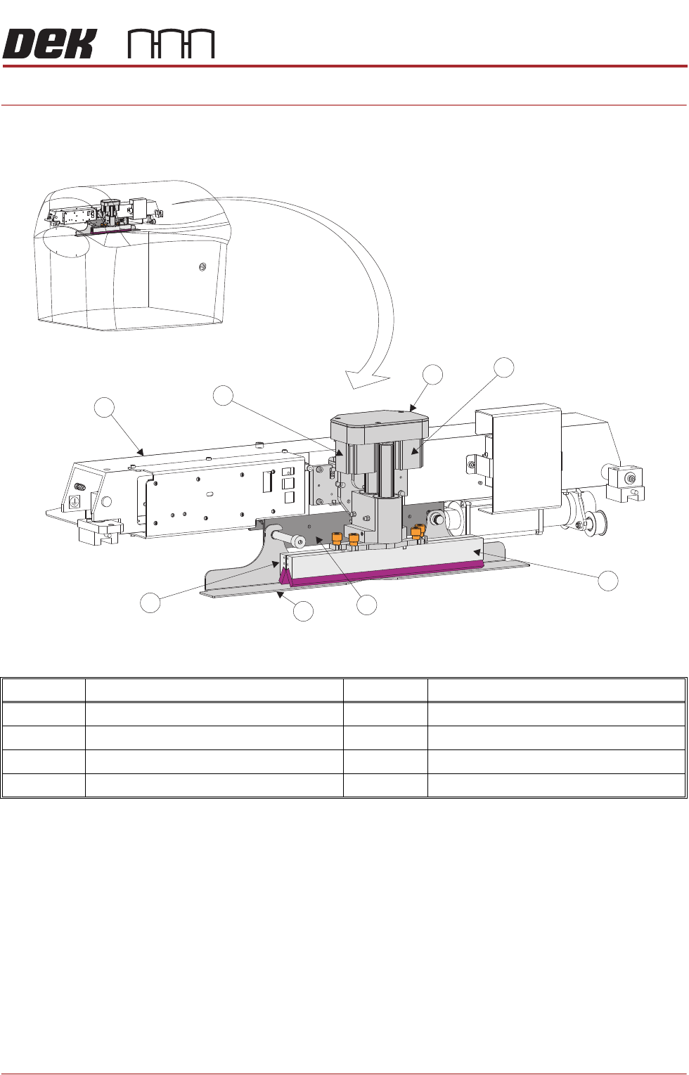
CHAPTER 9 SQUEEGEE MODULE
OVERVIEW
Item Description Item Description
1 Squeegee Printhead Mechanism 5 Squeegee Drip Tray
2 Rear Squeegee Stepper Motor 6 Rear Squeegee
3 Front Squeegee 7 Print Carriage
4 Squeegee Drip Tray Mechanism 8 Front Squeegee Stepper Motor
1
2
3
4
5
6
7
8
SQUEEGEE MODULE
OVERVIEW
9.2 Technical Reference Manual Chapter Issue 6, Jul 16
The squeegee mechanism is driven backwards and forwards across the stencil
by the print carriage.
The squeegee printhead mechanism incorporates two stepper motors to drive
the two squeegees independently down onto the stencil when a print stroke is
required. During the rearward stroke, the front squeegee is in contact with the
stencil performing a rear print stroke. During the forward stroke, the rear
squeegee is in contact with the stencil performing a forward print stroke.
The pressure being applied during the print stroke is measured by a strain
gauge bridge (located in the spring beam assembly of the squeegee mecha-
nism) and if necessary, a correction to the pressure is made by the software.
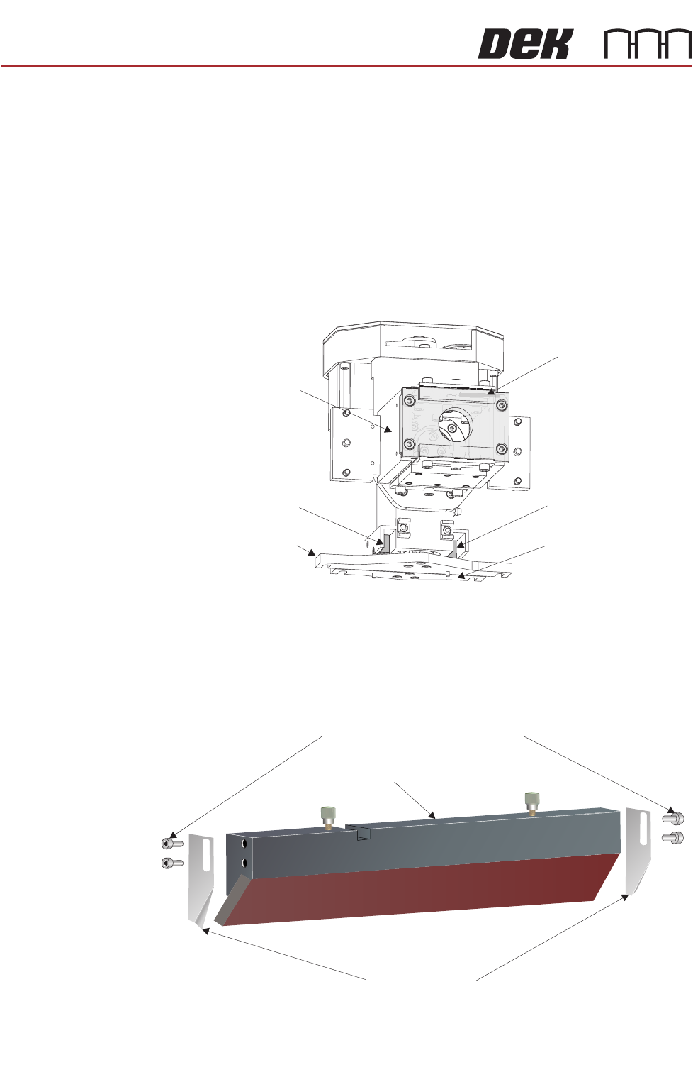
Figure 9-1 Squeegee Sensor Locations
Paste Deflectors Paste deflectors may be used to keep paste and low density print mediums in
front of the squeegees.
View on Rear of Squeegee Printhead Mechanism
Rear Squeegee Mount Front Squeegee Mount
Front Squeegee Home
Sensor
Rear Squeegee Home
Sensor
Spring Beam Assembly
(rear plate shown
transparent)
Strain Gauge Bridge
(inside spring beam
assembly)
Paste Deflector Securing Screws
Paste Deflectors
Squeegee