Micron Technical Reference V9 Volume 1.pdf - 第230页
SQUEEGEE MODULE OVERVIEW 9.2 Technical Reference Manual C hapter Issue 6, Ju l 16 The squeegee mechanism is drive n backwards and forwards across the stencil by the print carriage. The squeegee printhead mechanism incorp…
SQUEEGEE MODULE
OVERVIEW
Chapter Issue 6, Jul 16 Technical Reference Manual 9.1
CHAPTER 9 SQUEEGEE MODULE
OVERVIEW
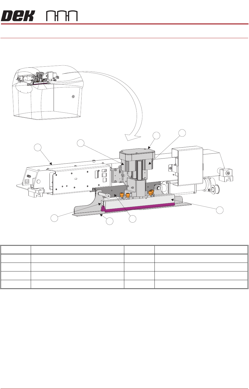
Item Description Item Description
1 Squeegee Printhead Mechanism 5 Squeegee Drip Tray
2 Rear Squeegee Stepper Motor 6 Rear Squeegee
3 Front Squeegee 7 Print Carriage
4 Squeegee Drip Tray Mechanism 8 Front Squeegee Stepper Motor
1
2
3
4
5
6
7
8
SQUEEGEE MODULE
OVERVIEW
9.2 Technical Reference Manual Chapter Issue 6, Jul 16
The squeegee mechanism is driven backwards and forwards across the stencil
by the print carriage.
The squeegee printhead mechanism incorporates two stepper motors to drive
the two squeegees independently down onto the stencil when a print stroke is
required. During the rearward stroke, the front squeegee is in contact with the
stencil performing a rear print stroke. During the forward stroke, the rear
squeegee is in contact with the stencil performing a forward print stroke.
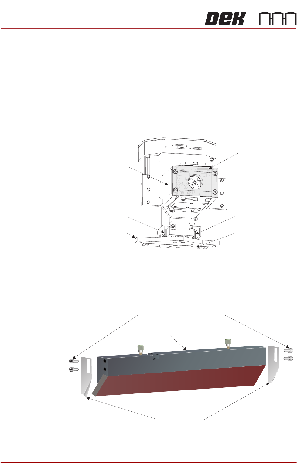
The pressure being applied during the print stroke is measured by a strain
gauge bridge (located in the spring beam assembly of the squeegee mecha-
nism) and if necessary, a correction to the pressure is made by the software.
Figure 9-1 Squeegee Sensor Locations
Paste Deflectors Paste deflectors may be used to keep paste and low density print mediums in
front of the squeegees.
View on Rear of Squeegee Printhead Mechanism
Rear Squeegee Mount Front Squeegee Mount
Front Squeegee Home
Sensor
Rear Squeegee Home
Sensor
Spring Beam Assembly
(rear plate shown
transparent)
Strain Gauge Bridge
(inside spring beam
assembly)
Paste Deflector Securing Screws
Paste Deflectors
Squeegee
SQUEEGEE MODULE
OVERVIEW
Chapter Issue 6, Jul 16 Technical Reference Manual 9.3
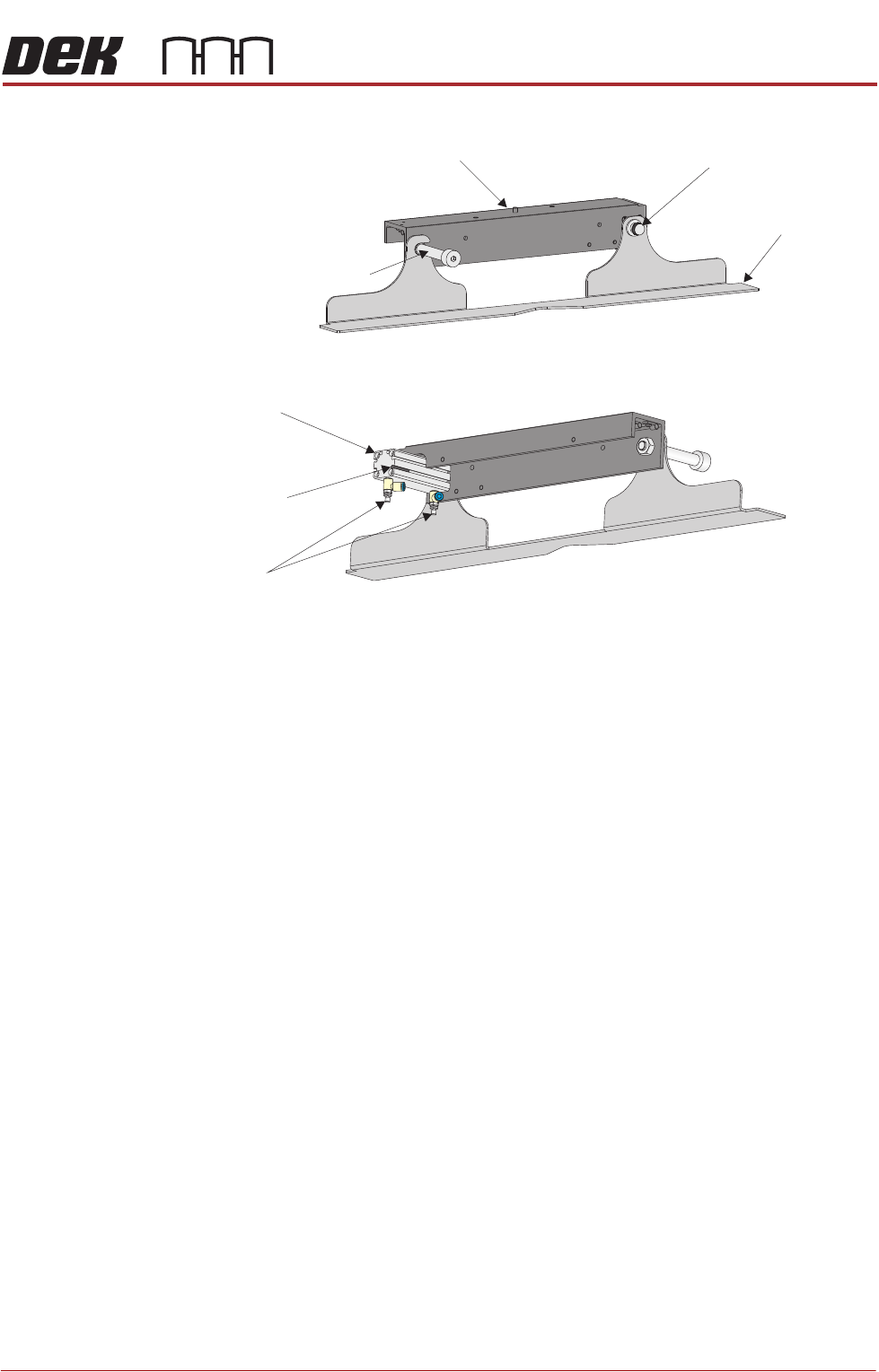
Squeegee Drip
Tray
Figure 9-2 Squeegee Drip Tray Overview
The squeegee drip tray mechanism secures to the underneath of the print
carriage. The drip tray pneumatic actuator extends the drip tray below the
squeegees to prevent print medium from dripping onto the stencil during print
carriage initialisation or auto stencil loading.
The squeegee drip tray mechanism is also used to accommodate the auto
screen loader mechanism, refer to the Adjustable Screen Mount (ASM) or Cast
C Chase Module chapters for more information.
The drip tray retracted sensor is used by software to check that the pneumatic
actuator has retracted the drip tray before lowering the squeegees.
NOTE
With the squeegee drip tray and the screen depth adjuster fitted, the ASM must
be set to 29 inches and cannot accommodate smaller stencil sizes.
View on Rear of Squeegee Drip Tray
View on Front of Squeegee Drip Tray
Squeegee
Drip Tray
Squeegee Drip Tray
Securing Screw
Drip Tray Guide Shaft
Drip Tray Pneumatic
Actuator
Drip Tray
Retracted Sensor
Speed
Control Valves
Squeegee Drip Tray Mechanism