Micron Technical Reference V9 Volume 1.pdf - 第232页
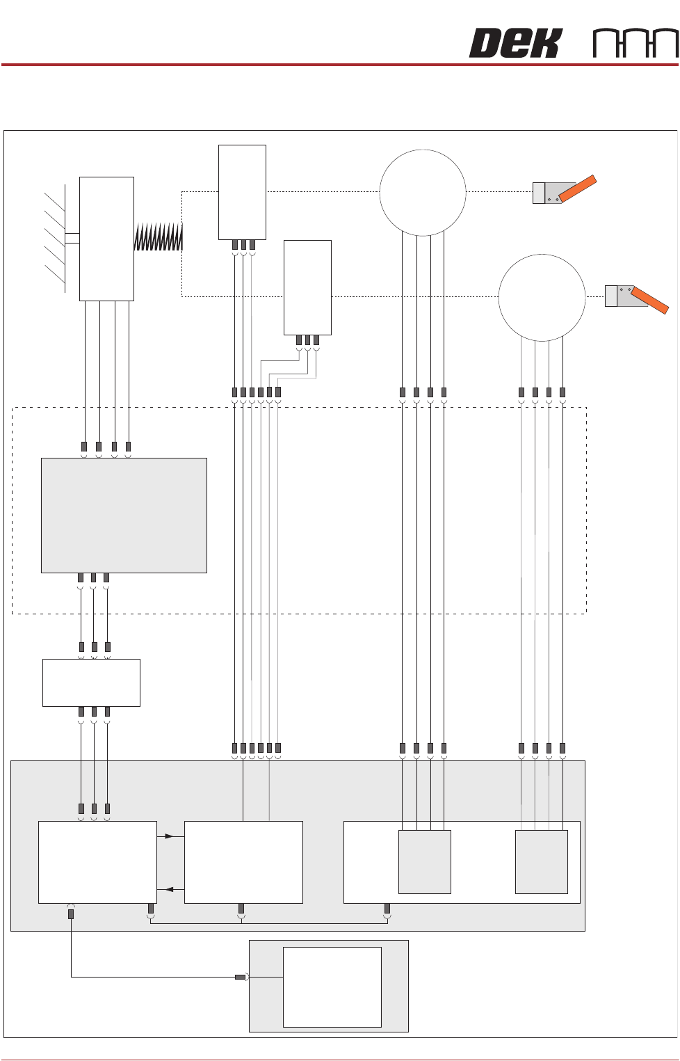
SQUEEGEE MODULE ELECTRICAL SCHEMATIC 9.4 Technical Reference Manual C hapter Issue 6, Ju l 16 ELECTRICAL SCHEMA TIC Squeegee Front Home (9SE04) Squeegee Rear Home (9SE05) Rear Squeegee Stepper Motor (9M4) Motor 1 B- Moto…
SQUEEGEE MODULE
OVERVIEW
Chapter Issue 6, Jul 16 Technical Reference Manual 9.3
Squeegee Drip
Tray
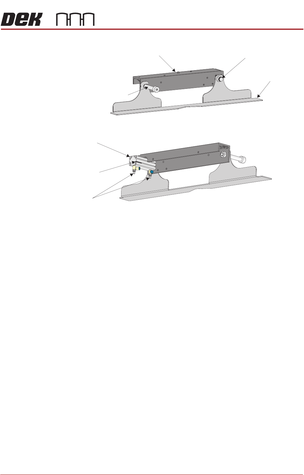
Figure 9-2 Squeegee Drip Tray Overview
The squeegee drip tray mechanism secures to the underneath of the print
carriage. The drip tray pneumatic actuator extends the drip tray below the
squeegees to prevent print medium from dripping onto the stencil during print
carriage initialisation or auto stencil loading.
The squeegee drip tray mechanism is also used to accommodate the auto
screen loader mechanism, refer to the Adjustable Screen Mount (ASM) or Cast
C Chase Module chapters for more information.
The drip tray retracted sensor is used by software to check that the pneumatic
actuator has retracted the drip tray before lowering the squeegees.
NOTE
With the squeegee drip tray and the screen depth adjuster fitted, the ASM must
be set to 29 inches and cannot accommodate smaller stencil sizes.
View on Rear of Squeegee Drip Tray
View on Front of Squeegee Drip Tray
Squeegee
Drip Tray
Squeegee Drip Tray
Securing Screw
Drip Tray Guide Shaft
Drip Tray Pneumatic
Actuator
Drip Tray
Retracted Sensor
Speed
Control Valves
Squeegee Drip Tray Mechanism
SQUEEGEE MODULE
ELECTRICAL SCHEMATIC
9.4 Technical Reference Manual Chapter Issue 6, Jul 16
ELECTRICAL SCHEMATIC
Squeegee Front
Home
(9SE04)
Squeegee Rear
Home
(9SE05)
Rear
Squeegee
Stepper
Motor
(9M4)
Motor 1 B-
Motor 1 B+
Motor 1 A-
Motor 1 A+
Motor 2 B-
Motor 2 B+
Motor 2 A-
Motor 2 A+
Print Carriage
9PL16
9PL08
9PL17
0V
+V
-IN
+IN
Strain Gauge Bridge
(9SE6)
Spring Beam
9SK11
9SK12
Print Carriage I/O
Node 3
N3PL16
M36PL35
N3SK2
N6PL3
CAN BUS
PC
Motherboard
M36PL35
USB
M36Pl28
NextMove ES
(I/O Node 1)
NextMove
Interface
Dual Stepper
Card X2
M36 Machine Control
Step 3
Step 4
Front
Squeegee
Stepper
Motor
(9M3)
M36PL21
M36PL12
M36PL21
CAN
In
Rising
Table
Node 6
N6SK2

SQUEEGEE MODULE
REPLACEMENT PROCEDURES
Chapter Issue 6, Jul 16 Technical Reference Manual 9.5
REPLACEMENT PROCEDURES
ProFlow to
Squeegees
Instances may occur when the machine is required to print using the squeegee
module configuration. The following procedure details how to revert the
machine from ProFlow use to the squeegee configuration:
Removing ProFlow 1. Select Maintenance.
2. Select Diagnostics.
3. Use Next or Previous to highlight ProFlow.
4. Select Select Module.
5. Ensure Home ProFlow is highlighted.
6. Select Run Diagnost.
7. Select Exit.
8. Select Exit.
9. Select Back.
10. Select Open Cover Commands.
11. Select Carriage To Front.
12. Select Back.
13. Select Shut Down and switch the mains isolator to OFF.