Micron Technical Reference V9 Volume 1.pdf - 第233页
SQUEEGEE MODULE REPLACEMENT PROCEDURES Chapter Issue 6, Jul 16 Technical Reference Manual 9.5 REPLACEMENT PROCE DURES ProFlow to Squeegees Instances may occur when the machine is required to prin t using the squeegee mod…
SQUEEGEE MODULE
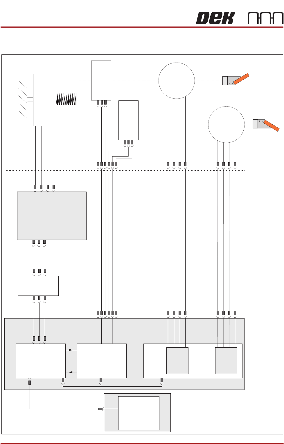
ELECTRICAL SCHEMATIC
9.4 Technical Reference Manual Chapter Issue 6, Jul 16
ELECTRICAL SCHEMATIC
Squeegee Front
Home
(9SE04)
Squeegee Rear
Home
(9SE05)
Rear
Squeegee
Stepper
Motor
(9M4)
Motor 1 B-
Motor 1 B+
Motor 1 A-
Motor 1 A+
Motor 2 B-
Motor 2 B+
Motor 2 A-
Motor 2 A+
Print Carriage
9PL16
9PL08
9PL17
0V
+V
-IN
+IN
Strain Gauge Bridge
(9SE6)
Spring Beam
9SK11
9SK12
Print Carriage I/O
Node 3
N3PL16
M36PL35
N3SK2
N6PL3
CAN BUS
PC
Motherboard
M36PL35
USB
M36Pl28
NextMove ES
(I/O Node 1)
NextMove
Interface
Dual Stepper
Card X2
M36 Machine Control
Step 3
Step 4
Front
Squeegee
Stepper
Motor
(9M3)
M36PL21
M36PL12
M36PL21
CAN
In
Rising
Table
Node 6
N6SK2

SQUEEGEE MODULE
REPLACEMENT PROCEDURES
Chapter Issue 6, Jul 16 Technical Reference Manual 9.5
REPLACEMENT PROCEDURES
ProFlow to
Squeegees
Instances may occur when the machine is required to print using the squeegee
module configuration. The following procedure details how to revert the
machine from ProFlow use to the squeegee configuration:
Removing ProFlow 1. Select Maintenance.
2. Select Diagnostics.
3. Use Next or Previous to highlight ProFlow.
4. Select Select Module.
5. Ensure Home ProFlow is highlighted.
6. Select Run Diagnost.
7. Select Exit.
8. Select Exit.
9. Select Back.
10. Select Open Cover Commands.
11. Select Carriage To Front.
12. Select Back.
13. Select Shut Down and switch the mains isolator to OFF.
SQUEEGEE MODULE
REPLACEMENT PROCEDURES
9.6 Technical Reference Manual Chapter Issue 6, Jul 16
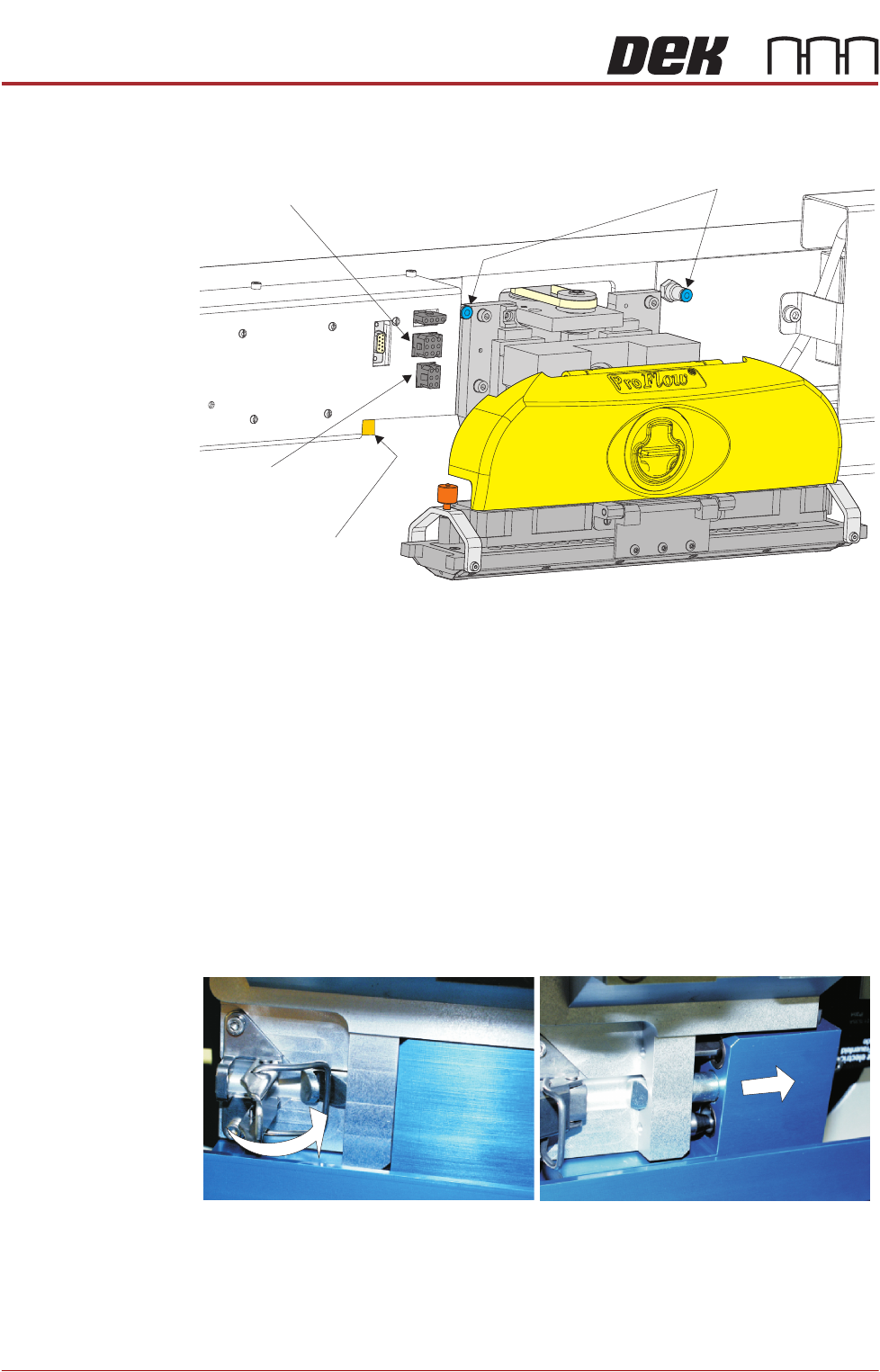
14. Disconnect both curly air lines from the self-seal pneumatic connectors
situated either side of the ProFlow printhead mechanism.
15. Disconnect the three ProFlow mechanism connectors from the print car-
riage, left hand side:
• ProFlow Motor
• Home Sensor
• ProFlow Paste Level Sensor (if Time to Go is enabled, an amplifier is
connected to 9PL61 and the connection is made to 9PL62 on the ampli-
fier).
16. Manually raise the ProFlow pressure mechanism by pulling the latch on the
front of the unit and lifting the mechanism to the fixed raised position.
17. Open the locking clip securing the transfer head to the pressure mechanism
and carefully slide the transfer head out and away from the pressure
mechanism as indicated in the figure below.
Pneumatic Connectors
ProFlow Motor
(9SK17)
Home Sensor
(9SK08)
ProFlow Paste Level
Sensor (9PL61)