Micron Technical Reference V9 Volume 1.pdf - 第235页
SQUEEGEE MODULE REPLACEMENT PROCEDURES Chapter Issue 6, Jul 16 Technical Reference Manual 9.7 18. R elease the pressure mechan ism from the printhead mechanism by unscrewing the two securing bolts, using a 5mm Al len key…
SQUEEGEE MODULE
REPLACEMENT PROCEDURES
9.6 Technical Reference Manual Chapter Issue 6, Jul 16
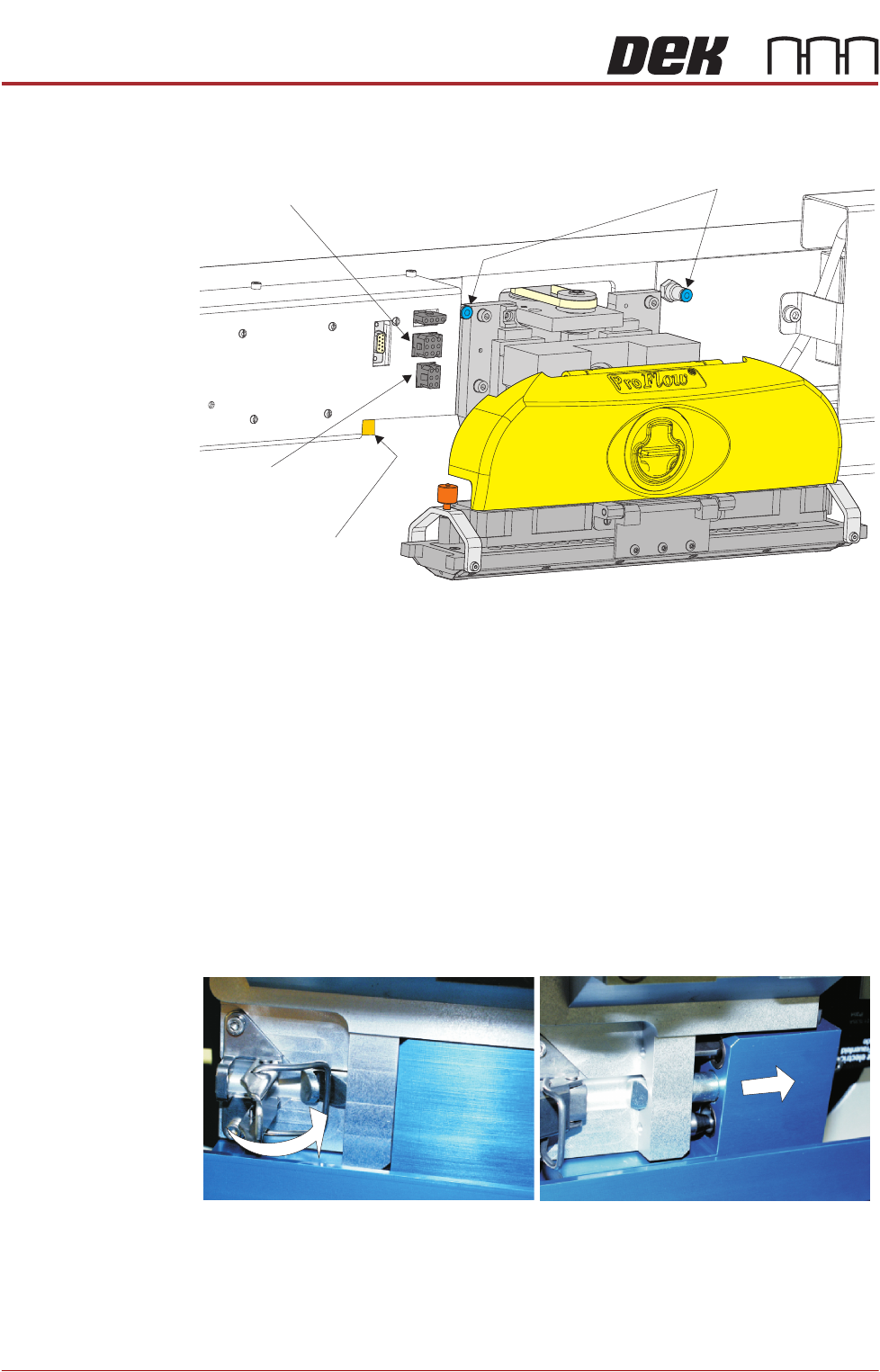
14. Disconnect both curly air lines from the self-seal pneumatic connectors
situated either side of the ProFlow printhead mechanism.
15. Disconnect the three ProFlow mechanism connectors from the print car-
riage, left hand side:
• ProFlow Motor
• Home Sensor
• ProFlow Paste Level Sensor (if Time to Go is enabled, an amplifier is
connected to 9PL61 and the connection is made to 9PL62 on the ampli-
fier).
16. Manually raise the ProFlow pressure mechanism by pulling the latch on the
front of the unit and lifting the mechanism to the fixed raised position.
17. Open the locking clip securing the transfer head to the pressure mechanism
and carefully slide the transfer head out and away from the pressure
mechanism as indicated in the figure below.
Pneumatic Connectors
ProFlow Motor
(9SK17)
Home Sensor
(9SK08)
ProFlow Paste Level
Sensor (9PL61)
SQUEEGEE MODULE
REPLACEMENT PROCEDURES
Chapter Issue 6, Jul 16 Technical Reference Manual 9.7
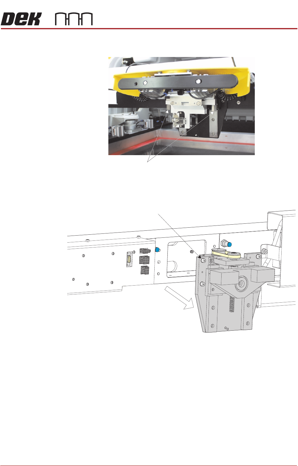
18. Release the pressure mechanism from the printhead mechanism by
unscrewing the two securing bolts, using a 5mm Allen key.
19. Loosen the four captive screws securing the ProFlow printhead mechanism
to the print carriage using a 4mm Allen key. Carefully remove the mecha-
nism from the print carriage.
Securing Bolts
Captive Screw (in 4 positions)
SQUEEGEE MODULE
REPLACEMENT PROCEDURES
9.8 Technical Reference Manual Chapter Issue 6, Jul 16
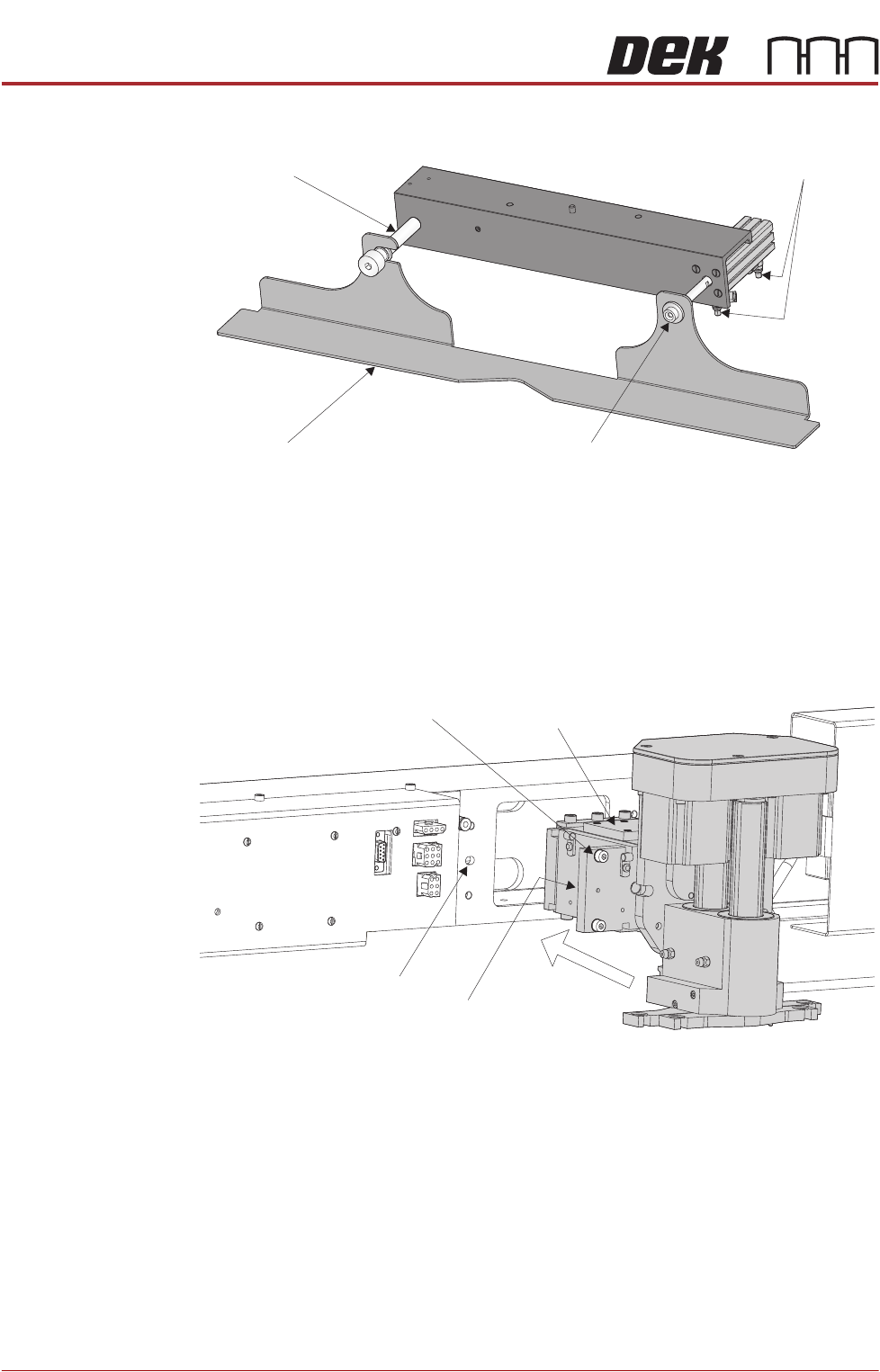
Fitting Drip Tray 1. Slide the slot in the drip tray onto the bearing on the drip tray guide shaft.
2. Secure the drip tray to the actuator piston using the securing screw.
3. Open the speed control valves on the drip tray actuator.
Fitting Squeegee 1. Carefully position the rear of the printhead mechanism (spring beam
assembly) into the print carriage so that both printhead mechanism dowels
locate into the print carriage locating holes. Secure the unit to the print
carriage by means of the four captive screws, ensuring the pneumatic pipe
is not trapped.
Drip Tray
Drip Tray Guide Shaft
Securing Screw
Speed Control Valves
Captive Screw (in 4 positions) Spring Beam Assembly
Locating Dowel
(in 2 positions)
Print Carriage Locating
Hole (in 2 positions)