Micron Technical Reference V9 Volume 1.pdf - 第237页
SQUEEGEE MODULE REPLACEMENT PROCEDURES Chapter Issue 6, Jul 16 Technical Reference Manual 9.9 2. Connect the following connectors to the print carriage, left hand side: • Rear Squeegee Motor • Front Squeegee Motor • Home…
SQUEEGEE MODULE
REPLACEMENT PROCEDURES
9.8 Technical Reference Manual Chapter Issue 6, Jul 16
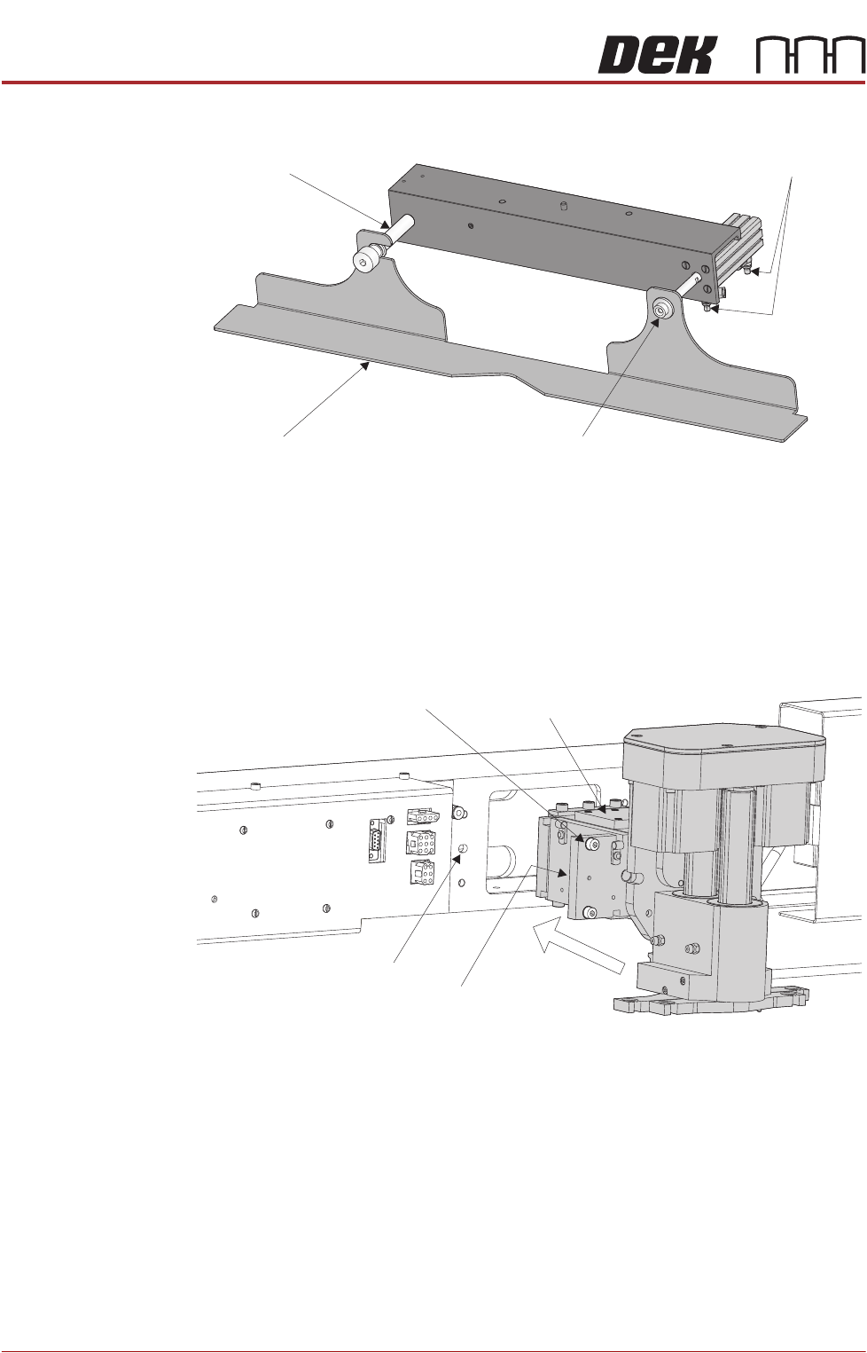
Fitting Drip Tray 1. Slide the slot in the drip tray onto the bearing on the drip tray guide shaft.
2. Secure the drip tray to the actuator piston using the securing screw.
3. Open the speed control valves on the drip tray actuator.
Fitting Squeegee 1. Carefully position the rear of the printhead mechanism (spring beam
assembly) into the print carriage so that both printhead mechanism dowels
locate into the print carriage locating holes. Secure the unit to the print
carriage by means of the four captive screws, ensuring the pneumatic pipe
is not trapped.
Drip Tray
Drip Tray Guide Shaft
Securing Screw
Speed Control Valves
Captive Screw (in 4 positions) Spring Beam Assembly
Locating Dowel
(in 2 positions)
Print Carriage Locating
Hole (in 2 positions)
SQUEEGEE MODULE
REPLACEMENT PROCEDURES
Chapter Issue 6, Jul 16 Technical Reference Manual 9.9
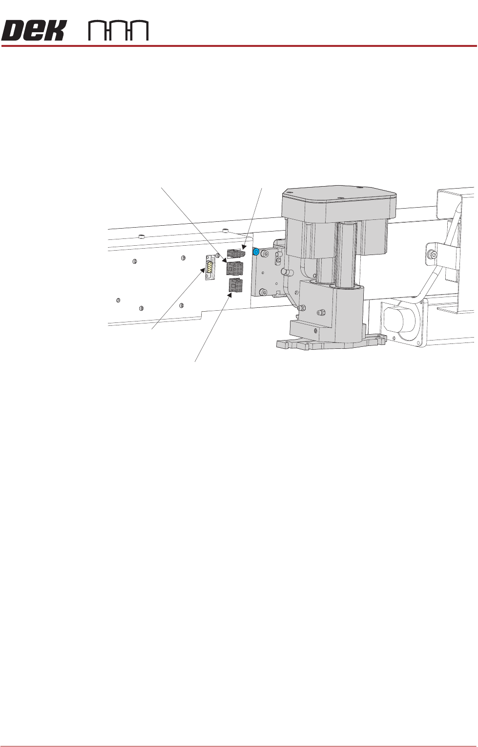
2. Connect the following connectors to the print carriage, left hand side:
• Rear Squeegee Motor
• Front Squeegee Motor
• Home Sensors
• Squeegee Pressure Amplifier
3. Fit the required configuration of squeegees to the printhead mechanism
squeegee mounts.
NOTE
Squeegee fitting information is detailed in the Replacement Procedures
section of this chapter.
4. Switch the mains isolator to ON and ensure that the machine recognizes the
squeegee module fit by displaying Squeegees Uninitialised during the
machine initialisation sequence.
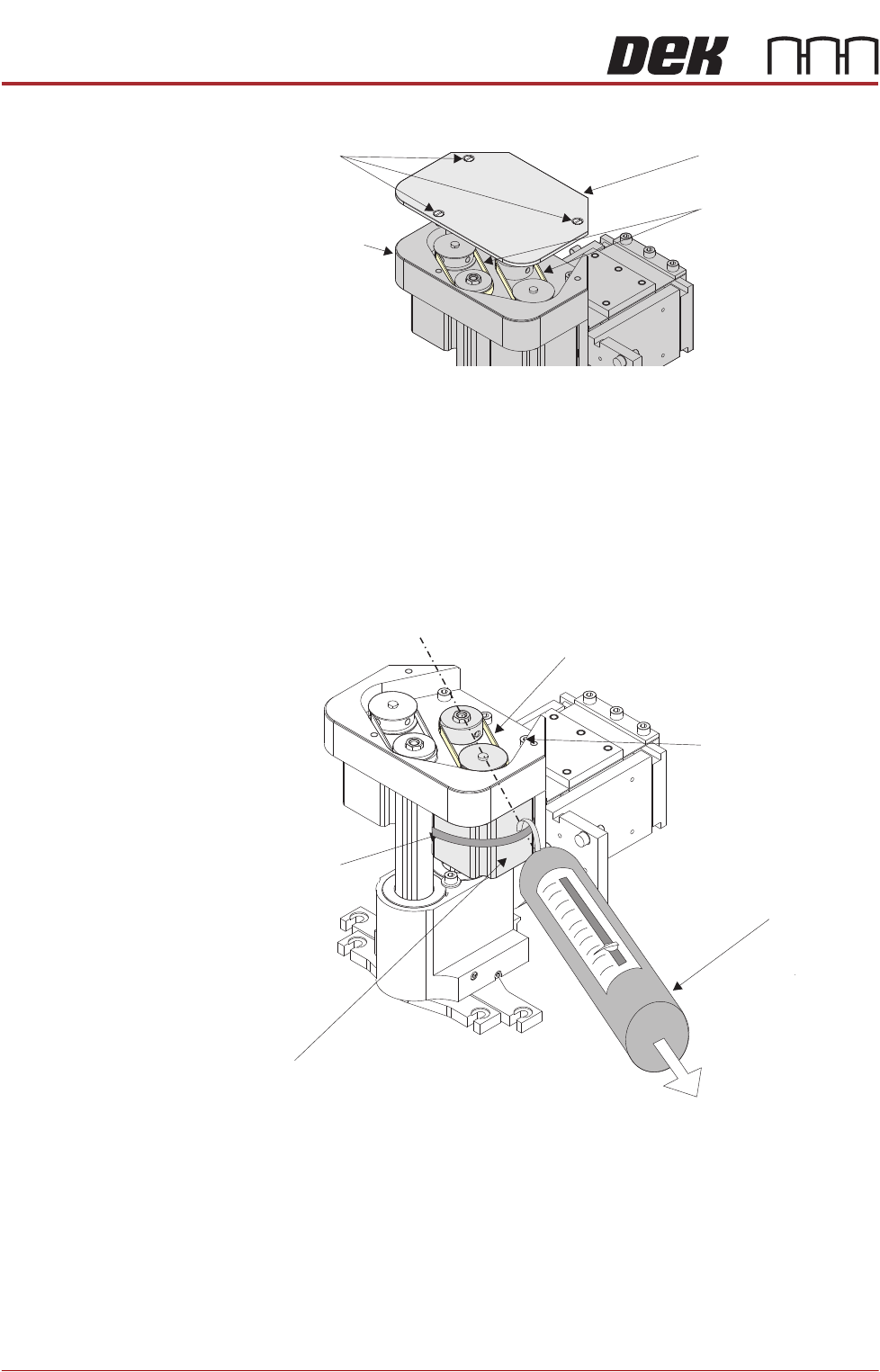
Drive Belt
Replacement
1. Select Open Cover Commands.
2. Select Carriage To Front.
3. Select Back.
4. Select Shut Down.
5. Select Continue.
6. Switch the mains isolator to OFF.
7. Open the front printhead cover.
8. Remove squeegees if fitted.
9. Remove the drive belt cover plate from the squeegee printhead mechanism
Rear Squeegee
Motor (9SK17)
Front Squeegee
Motor (9SK16)
Home Sensors
(9SK08)
Squeegee Pressure
Amplifier (N3SK16)
SQUEEGEE MODULE
REPLACEMENT PROCEDURES
9.10 Technical Reference Manual Chapter Issue 6, Jul 16
and remove the broken drive belt.
NOTE
In the drive belt replacement procedures, described below, the tensioning of the
belt only applies where the squeegee stepper motors are identified by the green
label shown in figure 9-3. For all other squeegee types, follow the ‘Alternative
Drive Belt Replacement’ procedure.
Rear Squeegee
Drive Belt
The rear squeegee drive belt (right hand stepper motor) can be replaced without
having to remove the printhead mechanism from the print carriage.
1. Slacken off the three screws securing the right hand motor to the motor
support plate.
2. Fit the new belt in position.
3. Using a cable tie wrap or similar, provide a loop around the top of the body
of the motor enabling the motor to be pulled using a force meter. Ensure
that the force meter is pulled in the direction which the drive belt is fitted,
figure above refers.
4. Pull the force meter until a tension of 3-4kgs is monitored on the meter.
Tighten the three screws whilst the motor is under tension.
Drive Belt Cover Plate
Drive Belts
Squeegee Printhead
Mechanism
Securing Screws
Tension in Direction of
Drive Belt Orientation
Right Stepper Motor
Rear Squeegee Motor Tensioning
Force Meter
Motor Securing Screw
Position (3 positions)
Looped CableTie
Drive Belt