Micron Technical Reference V9 Volume 1.pdf - 第242页
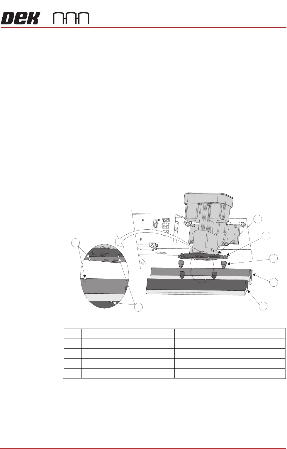
SQUEEGEE MODULE REPLACEMENT PROCEDURES 9.14 Technical Reference Manual Chapter Issue 6, Ju l 16 6. Fit the front squeegee to the front squeegee mount ensuring the thumb- screws are tightened finger tight. NOTE The lockin…
SQUEEGEE MODULE
REPLACEMENT PROCEDURES
Chapter Issue 6, Jul 16 Technical Reference Manual 9.13
Fitting the
Squeegees
It is usual to fit two trailing edge squeegees and use the machine in the Print/
Print mode.
When fitting a single squeegee (trailing edge or diamond section) to the
machine, it must be fitted to the front squeegee mount only.
The following procedure describes a double trailing edge squeegee configura-
tion fit to the machine printhead mounting assembly.
1. Select Product Setup.
2. Select Change Squeegees.
3. The print carriage is driven to the front position.
4. Open the front printhead cover.
5. Fit the rear squeegee to the rear squeegee mount tightening the thumb-
screws finger tight.
NOTE
The locking thumbscrews on the rear squeegee are positioned wider apart
than those fitted to the front squeegee and the keyway slot is positioned on
the left hand side of the rear squeegee.
Item Description Item Description
1 Front Squeegee Mount 5 Front Squeegee
2 Rear Squeegee Mount 6 Front Squeegee Key and Keyway Slot
3 Locking Thumbscrew (in 4 positions) 7 Rear Squeegee Key and Keyway Slot
4 Rear Squeegee
1
2
3
4
5
6
7

SQUEEGEE MODULE
REPLACEMENT PROCEDURES
9.14 Technical Reference Manual Chapter Issue 6, Jul 16
6. Fit the front squeegee to the front squeegee mount ensuring the thumb-
screws are tightened finger tight.
NOTE
The locking thumbscrews on the front squeegee are positioned closer
together than those fitted to the rear squeegee and the keyway slot is
positioned on the right hand side of the front squeegee.
7. Close the front printhead cover.
8. Press the System button.
9. Select Continue.
10. Select Back.
11. Carry out Squeegee Reference Height calibration, Calibrations section of
this chapter refers.
SQUEEGEE MODULE
CALIBRATIONS
Chapter Issue 6, Jul 16 Technical Reference Manual 9.15
CALIBRATIONS
Squeegee
Pressure
Calibration
Squeegee pressure calibration is carried out on machines, fitted with the
Pressure Hardware option, after the following circumstances:
• The squeegee mechanism is replaced
• The strain gauge bridge in the squeegee mechanism is replaced
• The rising table sensors have been replaced or adjusted
A force meter calibration jig and squeegee pressure plate are required to
perform the squeegee pressure calibration.
NOTE
1. Ensure that the rising table print reference height is set correctly before
commencing, (the calibration relies upon accurate positioning of the table to
make a reference).
2. Ensure that the Pressure Hardware parameter in Maintenance\Machine
Setup\Options is set to FITTED.
Use the following procedure to calibrate the squeegee pressure:
WARNING
BOARD CLAMPS. EXTREME CARE MUST BE EXERCISED WHEN WORKING IN
THE TOOLING AREA OF THE MACHINE TO AVOID INJURY. THE FOILS ON THE
FRONT AND REAR BOARD CLAMPS ARE VERY SHARP.
1. Select Open Cover Commands.
2. Select Carriage To Rear.
3. Select Unload Screen.
4. Open the front printhead cover.
5. Remove the stencil from the machine.
6. Remove the tooling from the manual tooling plate.
7. Close the front printhead cover.
8. Press the System button.
9. Select Back.
10. Select Maintenance.
11. Select Calibrations.
12. Select Pressure.
13. Select Calibrat Readings.
The rails are checked for the presence of a board, the print carriage moves
to the calibration position, the rear rail moves to home position, the table
homes and the board clamps are closed.
14. The machine cover is unlocked and the message ‘Fit the pressure calibra-
tion rig’ is displayed with the following window:
CALIBRATION DATA
Gain Factor
1.02