Micron Technical Reference V9 Volume 1.pdf - 第245页
SQUEEGEE MODULE CALIBRATIONS Chapter Issue 6, Jul 16 Technical Reference Manual 9.17 17. Fit the calibration jig to the front squeegee position. 18. Fit the squeegee pressure plate to the rising table ensuring that the l…
SQUEEGEE MODULE
CALIBRATIONS
9.16 Technical Reference Manual Chapter Issue 6, Jul 16
15. Open the front printhead cover.
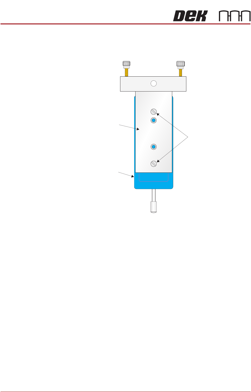
16. Ensure that the calibration jig is secured to the mounting plate as shown in
the following graphic:
Mounting Plate
Mounting Holes
Calibration Jig
A
A
S
S
SQUEEGEE MODULE
CALIBRATIONS
Chapter Issue 6, Jul 16 Technical Reference Manual 9.17
17. Fit the calibration jig to the front squeegee position.
18. Fit the squeegee pressure plate to the rising table ensuring that the locating
dowels insert the holes of the rising table.
NOTE
During the squeegee pressure calibration the dwell height of the rear
squeegee is 15mm regardless of the set up value. This height is set during
calibration only.
19. Switch the force meter ON and check the reading is 0kg, (ensure the force
meter is not in contact with the squeegee pressure plate).
20. Select Continue.
21. The front squeegee mechanism steps down until a change in pressure is
detected and continues stepping down until the pressure value stored on the
machine is reached. If the calibration jig displays 10kg, go to Step 25.
22. Select Jog Rig.
23. Use the left and right jog buttons to move the front squeegee mechanism up
or down until the calibration jig displays 10kg.
NOTE
Achieving exactly 10kg may not be possible as some calibration jigs display
down to three decimal places.
24. Select Set Calib..
25. Select Exit.
26. The front squeegee mechanism moves to the home position. The message
‘Confirm that the pressure calibration jig has been removed.’ is dis-
played.
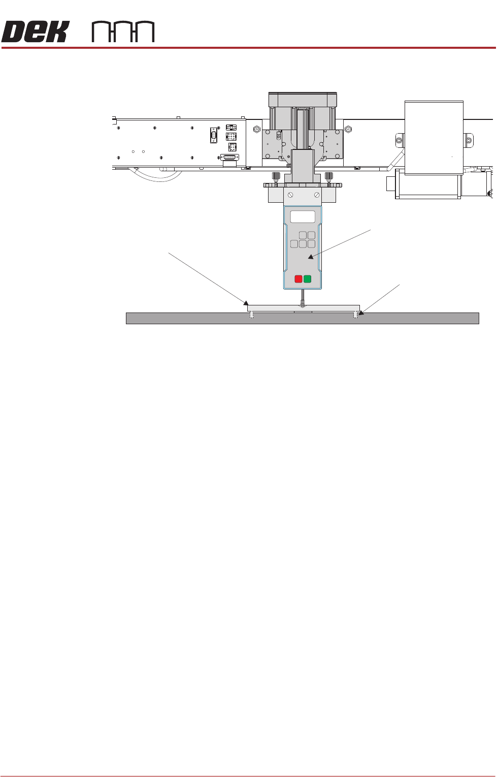
View on Front of Rising Table and Squeegee Mechanism
Squeegee Pressure Plate
Locating Dowel
(in 2 positions)
O
OFF
I
ON
UNITS
Zero
MAXTXD
RESET
00.00
Portable Force Gauge
(Calibration Jig)

SQUEEGEE MODULE
CALIBRATIONS
9.18 Technical Reference Manual Chapter Issue 6, Jul 16
27. Remove the calibration jig and the squeegee pressure plate from the
machine. On completion select Yes, the table resets, the print carriage
moves to home position, board clamps open and the rear rail moves to the
board width setting.
28. Carry out the Squeegee Reference Height (Pressure Feedback) calibration.
Squeegee
Reference Height
(Pressure
Feedback)
Squeegee reference height is carried out on machines fitted with the Pressure
Hardware option after the following circumstances:
• Squeegee pressure calibration
• Squeegee change
Use the following procedure to set the squeegee reference height:
1. If a Ptest.dat file is not required, go to Step 7.
2. Select Maintenance.
3. Select Test Cycles.
4. Select Data Logging On.
5. Select Back.
6. Select Back.
7. Select Setup Product.
8. Select Squeegees.
9. Select Unload Screen.
10. Open the front printhead cover.
11. Remove the stencil from the machine.
12. Close the front printhead cover.
13. Press the System button.
14. Select Calibrate Heights.
15. The message ‘Ensure that the correct squeegees are fitted!’ is dis-
played.
16. Fit the required squeegees to the front and rear squeegee mounts as
detailed in the Replacement Procedures section of this chapter.
17. Select Continue.
18. The following machine sequence is carried out:
a. The rails are checked for the presence of a board.
b. The rising table is driven to print height.
c. The board clamps are closed.
d. The print carriage drives the front squeegee over the front rail; see note.
e. The rear squeegee is driven down to dwell height.
f. The front squeegee is driven down by the stepper motor until contact with
the board clamp is made.
g. The front squeegee continues to be driven down until a 2kg pressure
difference is detected, the motor pauses.