Micron Technical Reference V9 Volume 1.pdf - 第247页
SQUEEGEE MODULE CALIBRATIONS Chapter Issue 6, Jul 16 Technical Reference Manual 9.19 h. The amount of steps (t he stepper motor took to get to this positio n) and the pressure are recorded. i. The stepper motor drives do…

SQUEEGEE MODULE
CALIBRATIONS
9.18 Technical Reference Manual Chapter Issue 6, Jul 16
27. Remove the calibration jig and the squeegee pressure plate from the
machine. On completion select Yes, the table resets, the print carriage
moves to home position, board clamps open and the rear rail moves to the
board width setting.
28. Carry out the Squeegee Reference Height (Pressure Feedback) calibration.
Squeegee
Reference Height
(Pressure
Feedback)
Squeegee reference height is carried out on machines fitted with the Pressure
Hardware option after the following circumstances:
• Squeegee pressure calibration
• Squeegee change
Use the following procedure to set the squeegee reference height:
1. If a Ptest.dat file is not required, go to Step 7.
2. Select Maintenance.
3. Select Test Cycles.
4. Select Data Logging On.
5. Select Back.
6. Select Back.
7. Select Setup Product.
8. Select Squeegees.
9. Select Unload Screen.
10. Open the front printhead cover.
11. Remove the stencil from the machine.
12. Close the front printhead cover.
13. Press the System button.
14. Select Calibrate Heights.
15. The message ‘Ensure that the correct squeegees are fitted!’ is dis-
played.
16. Fit the required squeegees to the front and rear squeegee mounts as
detailed in the Replacement Procedures section of this chapter.
17. Select Continue.
18. The following machine sequence is carried out:
a. The rails are checked for the presence of a board.
b. The rising table is driven to print height.
c. The board clamps are closed.
d. The print carriage drives the front squeegee over the front rail; see note.
e. The rear squeegee is driven down to dwell height.
f. The front squeegee is driven down by the stepper motor until contact with
the board clamp is made.
g. The front squeegee continues to be driven down until a 2kg pressure
difference is detected, the motor pauses.
SQUEEGEE MODULE
CALIBRATIONS
Chapter Issue 6, Jul 16 Technical Reference Manual 9.19
h. The amount of steps (the stepper motor took to get to this position) and
the pressure are recorded.
i. The stepper motor drives downwards another 15 steps, this is recorded
with the pressure detected. This is repeated a further 18 times to achieve
a total of 20 results.
NOTE
If Over the Top Snuggers are fitted, the front squeegee is calibrated on
the rear rail, the rear squeegee is calibrated on the front rail.
19. The rear squeegee is calibrated in a similar manner.
20. The message ‘Calibrate Squeegee heights complete’ is displayed.
21. Select Back.
22. Select Back.
23. Select Maintenance.
24. Select Test Cycles.
25. Select Data Logging Off.
26. Select Back.
27. Select Back.
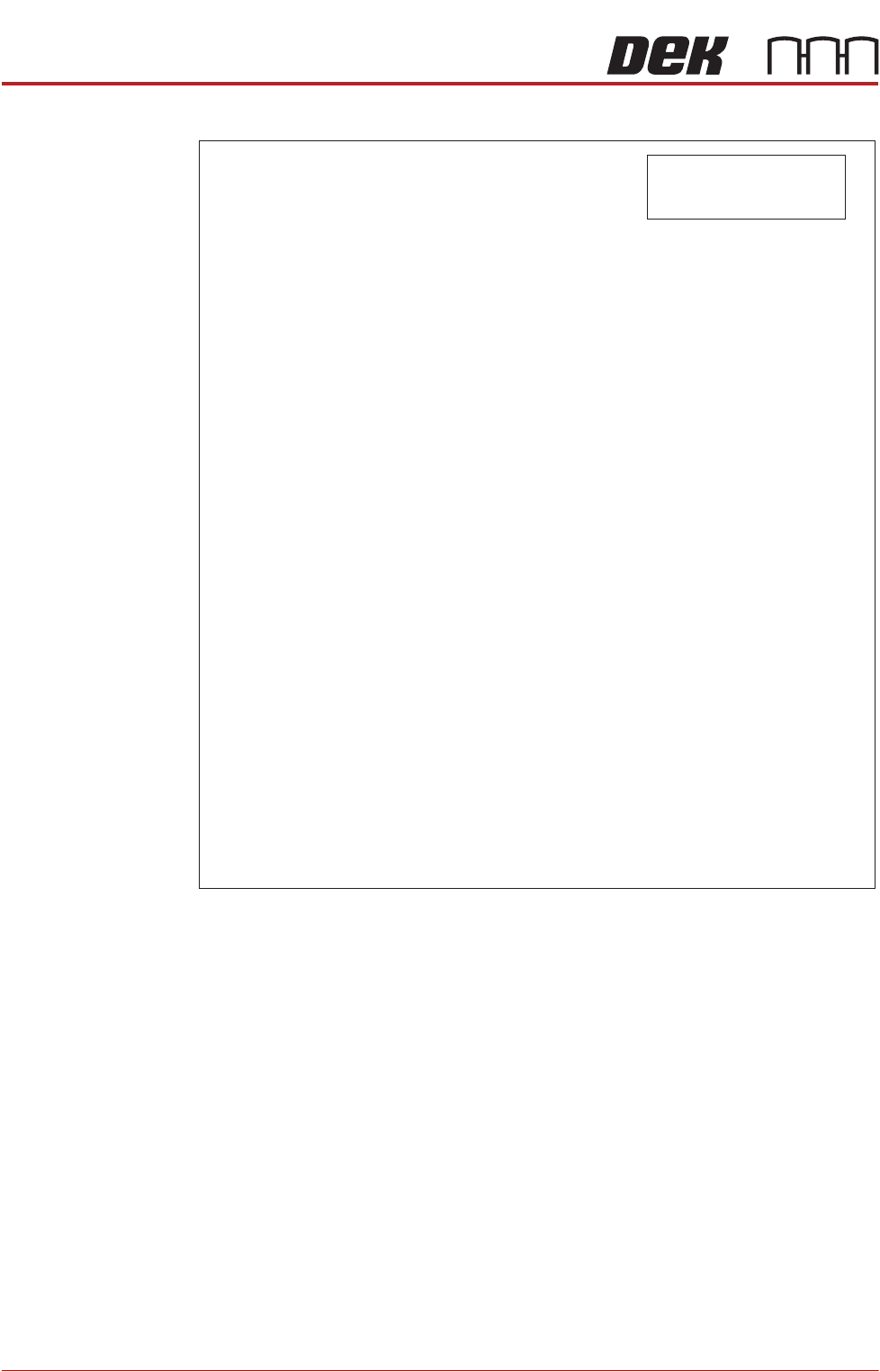
Ptest.dat File The file displays 20 front squeegee readings followed by 20 rear squeegee
readings, showing the relationship between steps (displacement) and pressure
applied. From the readings taken, the front and rear pressure factors and
squeegee reference heights are calculated. At the end of the file, 5 readings of
flood pressure and reference height readings are displayed (these are also
listed in the Config.txt file).
The Ptest.dat file is located on the hard drive of the machine PC. To view the
file carry out the following procedure:
1. From the Windows start menu, select Programs - Accessories - Windows
Explorer.
2. Under My Computer, locate and open the E:\Log\Ptest.dat file.
SQUEEGEE MODULE
CALIBRATIONS
9.20 Technical Reference Manual Chapter Issue 6, Jul 16
The figure below gives a representation of the Ptest.dat file.
Squeegee
Reference Height
(Non Pressure
Feedback)
The squeegee reference height is carried out after a squeegee change on
machines without the Pressure Hardware option. This procedure must be used
if Pressure Hardware is disabled.
Use the following procedure to set the squeegee reference height:
1. Select Open Cover Commands.
2. Select Carriage To Front.
3. Select Unload Screen.
4. Open the front printhead cover.
5. Remove the stencil from the machine.
6. Fit the required squeegees to the front and rear squeegee mounts as
detailed in the Replacement Procedures section of this chapter.
7. Close the front printhead cover.
8. Press the System button.
9. Select Back.
10. Select Setup Product.
(Fwd Press Flood) (Rear Press Flood) (Flood Ref. Height) (Front Ref. Height) (Rear Ref. Height)
33.1004 31.9668 3951.6971 3947.7037 3935.1178
(steps)
(kg)
Rear Squeegee
4301.000000
4286.000000
4271.000000
4256.000000
4241.000000
4226.000000
4211.000000
4196.000000
4181.000000
4166.000000
4151.000000
4136.000000
4121.000000
4106.000000
4091.000000
4076.000000
4061.000000
4046.000000
4031.000000
4016.000000
22.480215
21.961163
21.503175
21.045188
20.587201
20.068149
19.640694
19.182706
18.724719
18.266732
17.747680
17.289692
17.801172
16.343185
15.885198
15.396678
14.908158
14.480703
13.992184
13.564729
Front Squeegee
(steps)
(kg)
4039.000000
4324.000000
22.388617
21.930630
21.472643
21.045188
20.587201
20.129213
19.640694
19.213239
18.694187
18.266732
17.839277
17.350757
16.892770
16.465315
16.007328
15.579873
15.121886
14.724963
14.236444
13.778456
4309.000000
4294.000000
4279.000000
4264.000000
4249.000000
4234.000000
4219.000000
4204.000000
4189.000000
4174.000000
4159.000000
4144.000000
4129.000000
4114.000000
4099.000000
4084.000000
4069.000000
4054.000000
NOTE
Text shown in italics is not
displayed in the Ptest.dat file.