Micron Technical Reference V9 Volume 1.pdf - 第25页
SAFETY FEATURES PRINTER SAFETY FEATURES Chapter Issue 14, Feb 18 Technical Reference Manual 2.1 CHAPTER 2 SA FETY FEA TURES PRINTER SAFETY FEA TURES Introduction This section describes the various safety features that ar…
INTRODUCTION
GLOSSARY
1.14 Technical Reference Manual Chapter Issue 12, Feb 18
OTS Over the Top Snugger. System for holding the product over the top until the snugger actuates
Parameter Variable quantity which once set becomes the datum for other mathematical functions.
Paste Roll Height
Monitor
A system which measures the paste roll. The user can program the print cycle to apply more paste
exactly when it is needed most.
ProFlow Provides enclosed head print medium management. Three models are available - Classic,
ProFlow ATx and Proflow Tx; across the range they print a variety of material viscosities.
Print Medium The material used to print/transfer onto a board, wafer or substrate - Pastes/Adhesives/Enzymes/
Inks.
QC Calc External computer program that provides statistical analysis of certain printer functions.
RTC Rapid Transit Conveyor. A programmable width conveyor system, which can accommodate up to
three boards in the printer at one time, thereby reducing the printer cycle time
ROI Region of Interest. An area representing the current 2D inspection site superimposed on both the
stencil and board images within the vision data window.
SCAR Software Controlled Air Regulator. A software controlled regulator used to control various ProFlow
pressure settings.
Schematic Representational diagram of a system.
Screen An emulsion coated mesh of various thicknesses, stretched onto a frame with an image photo-
graphically processed into the emulsion, through which solder paste or other media can be
deposited in a controlled fashion onto a board or other surface. (see also Stencil)
SMEMA Surface Mount Equipment Manufacturer Association. A standard type of FMI protocol.
SMPSU Switched Mode Power Supply Unit, situated in the printer power supply module. Produces various
dc voltages for the printer.
SPC Statistical Process Control. Collection of outputs from the printer used by QC Calc program.
Squeegee Device, usually rubber or metal used to distribute printable material across and through the stencil
during the print cycle.
Stencil A shim, usually metal that has an appropriate image cut through it. The shim is secured to a metal
frame through which solder paste or such media, can be deposited in a controlled fashion onto a
board or other such surface.
Stinger Adhesive dot deposition system
TCM Temperature Control Module. An external device that connects to the DEK printer controlling the
temperature within the printer.
TRS Topside Reference System. Allows multiple substrates to be printed accurately in a single print
cycle.
Upline A term referring to an item or piece of equipment within a production line situated above the DEK
printer moving against the direction of the line towards the beginning of the line.
USB Universal Serial Bus. The USB is a 2 wire data link designed for 2 way communications between
the printer PC and the following: M36 printer controller; M37 power supply; 4 port USB hub.
USC Under Screen Cleaner. A programmable module for cleaning the underside of a screen/stencil.
Term Definition
SAFETY FEATURES
PRINTER SAFETY FEATURES
Chapter Issue 14, Feb 18 Technical Reference Manual 2.1
CHAPTER 2 SAFETY FEATURES
PRINTER SAFETY FEATURES
Introduction This section describes the various safety features that are incorporated into the
printer to provide a safe operating and maintenance environment.
Safety Notices Safety notices in the form of PROHIBITION, WARNING, CAUTION and MAN-
DATORY labels are placed on the printing printer and notices are posted
throughout the associated documentation to alert the operator/maintainer to
possible hazards which may cause physical injury or equipment damage.
The following label illustrated below, may be fitted to the printer, this signifies
that the user should refer to the relevant section of the Technical Reference
Manual before attempting to carry out work on the equipment.
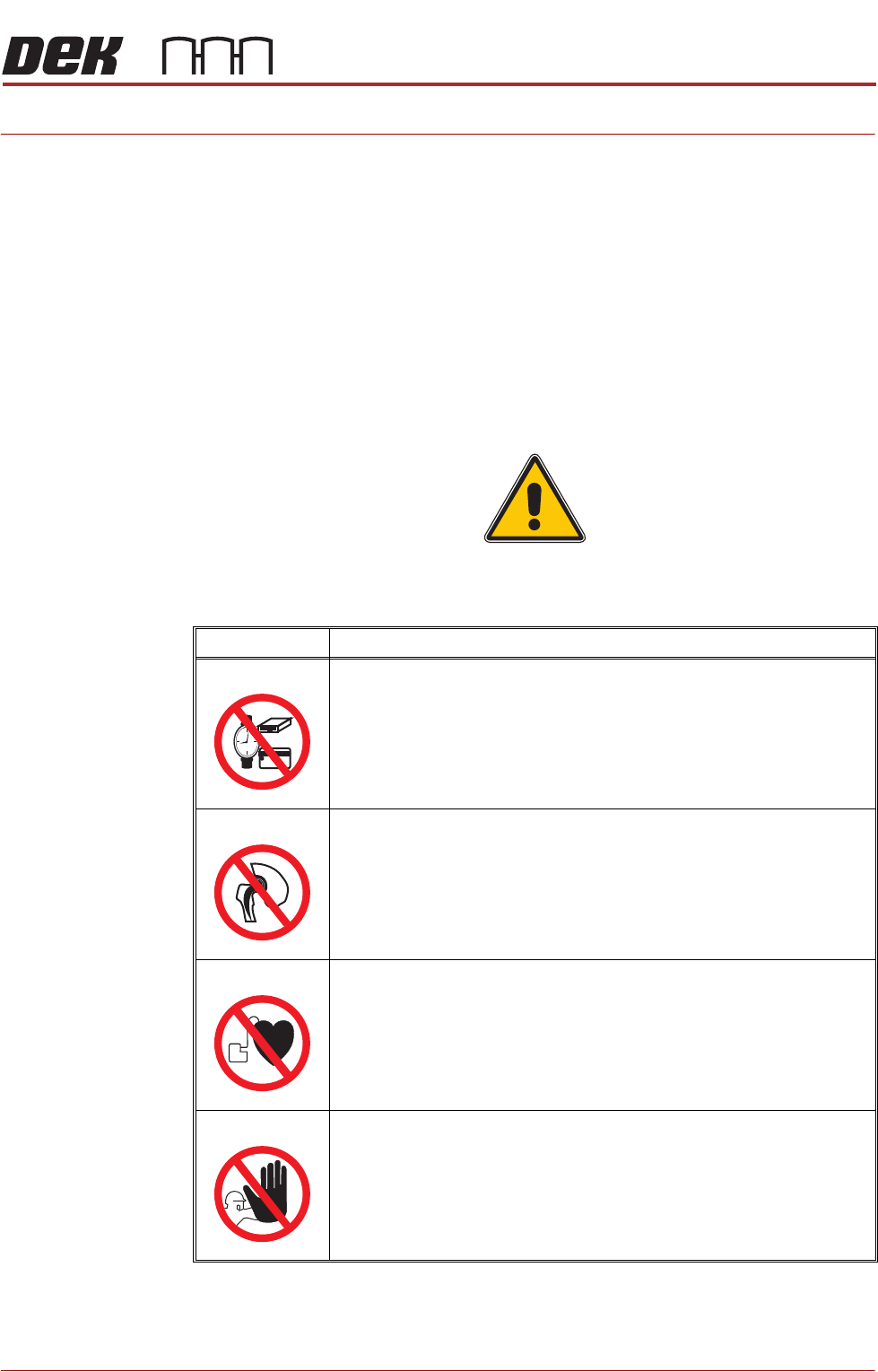
Prohibition Notices Prohibition notices draw the attention of users/maintainers to prohibiting behav-
iour likely to cause a risk to health or safety. The following table displays the
prohibition labels affixed to printer and displayed in the printer documentation:
SYMBOL DEFINITION
PROHIBITION
STRONG MAGNETIC FIELD. A STRONG MAGNETIC FIELD EXISTS IN
THE VICINITY OF THE LINEAR MOTORS THAT MAY ACT UPON FER-
ROUS OBJECTS WHOSE MOVEMENTS COULD LEAD TO PERSONAL
INJURY AND/OR DAMAGE TO THE MACHINE.
PROHIBITION
STRONG MAGNETIC FIELD. A STRONG MAGNETIC FIELD EXISTS IN
THE VICINITY OF THE LINEAR MOTORS THAT REPRESENT A SERI-
OUS HAZARD TO PEOPLE FITTED WITH METALLIC IMPLANTS.
PROHIBITION
ELECTROMAGNETIC FIELD. AN ELECTROMAGNETIC FIELD EXISTS
WITHIN THE MACHINE FROM THE LINEAR MOTORS. THESE MAY
PRESENT A HAZARD TO PEOPLE FITTED WITH AN IMPLANTED CAR-
DIAC DEVICE. THE MOTOR MANUFACTURER RECOMMENDS A SAFE
DISTANCE OF AT LEAST 15MM.
PROHIBITION
MACHINE COVERS. IN ORDER TO PROTECT PERSONNEL AND TO
PREVENT DAMAGE TO THE MACHINE, COVERS ARE FITTED TO THE
MACHINE FRAME. THESE PANELS MUST ONLY BE REMOVED BY
SUITABLY QUALIFIED PERSONNEL.
SAFETY FEATURES
PRINTER SAFETY FEATURES
2.2 Technical Reference Manual Chapter Issue 14, Feb 18
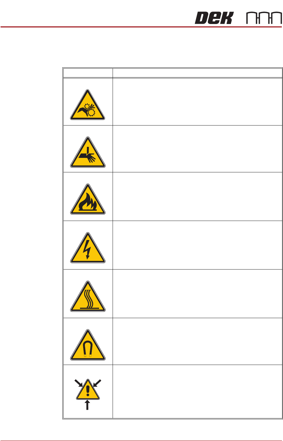
Warning Notices Warning notices draw the attention of users/maintainers to a potentially hazard-
ous situation which, if not avoided, could result in death or serious injury. The
following table displays the warning labels affixed to the printer and/or displayed
in the printer documentation:
SYMBOL DEFINITION
WARNING
MOVING PARTS. MOVING PARTS ARE PRESENT IN THE VICINITY
OF THIS WARNING LABEL, THESE PARTS HAVE THE POTENTIAL
TO CAUSE INJURY.
WARNING
BOARD CLAMPS. EXTREME CARE MUST BE EXERCISED WHEN
WORKING IN THE TOOLING AREA OF THE MACHINE TO AVOID
INJURY. THE FOILS ON THE FRONT AND REAR BOARD CLAMPS
ARE VERY SHARP.
WARNING
FLAMMABLE. FLAMMABLE SUBSTANCES ARE PRESENT. KEEP
AWAY FROM HEAT, SOURCES OF IGNITION AND STATIC DIS-
CHARGES. USE IN A WELL VENTILATED AREA.
WARNING
LETHAL VOLTAGE. DANGEROUS VOLTAGES EXIST IN THIS EQUIP-
MENT. ENSURE ALL ELECTRONIC COVERS AND MAIN MACHINE
COVERS ARE FITTED BEFORE OPERATING THIS EQUIPMENT.
WARNING
HOT SURFACES. THE SURFACE OF THIS COMPONENT OR SUR-
ROUNDING AREA MAY BECOME HOT DURING PROLONGED OPER-
ATION. CARE TO BE TAKEN WHEN WORKING IN THE VICINITY OF
THIS COMPONENT.
WARNING
STRONG MAGNET FIELD. A STRONG MAGNETIC FIELD EXISTS IN
THE VICINITY OF THE LINEAR MOTORS. THIS MAY PRESENT A
HAZARD TO PERSONNEL OR EQUIPMENT.
WARNING
COMPRESSED AIR. COMPRESSED AIR SHOULD NEVER IMPINGE
UPON THE BODY. PORTS, PIPES, ETC MUST NEVER BE BLOCKED
BY HAND. BEFORE CONNECTING OR DISCONNECTING ANY
PNEUMATIC COMPONENTS, ENSURE THE COMPRESSED AIR
SUPPLY HAS BEEN DISSIPATED AND DISCONNECTED FROM THE
MACHINE.
))
((