Micron Technical Reference V9 Volume 1.pdf - 第252页
PROACTIV OVERVIEW 10.2 Technical Reference Manual Chapter Issue 5, Jan 15 Elements The ProActiv module consists of: • A squeegee mechanism to house the sensors • Electronic control modules and associated wiring looms • A…
PROACTIV
OVERVIEW
Chapter Issue 5, Jan 15 Technical Reference Manual 10.1
CHAPTER 10 PROACTIV
OVERVIEW
Introduction ProActiv™ is an active squeegee module. The ProActiv mount assembly (which
is similar to the standard squeegee mount and shares common functionality and
construction), houses the active squeegees. The difference is apparent when
using ProActiv during a print stroke, the squeegee blade is activated, this
provides additional forces in the print direction; it modifies the rheology of the
solder paste increasing its fluidity.
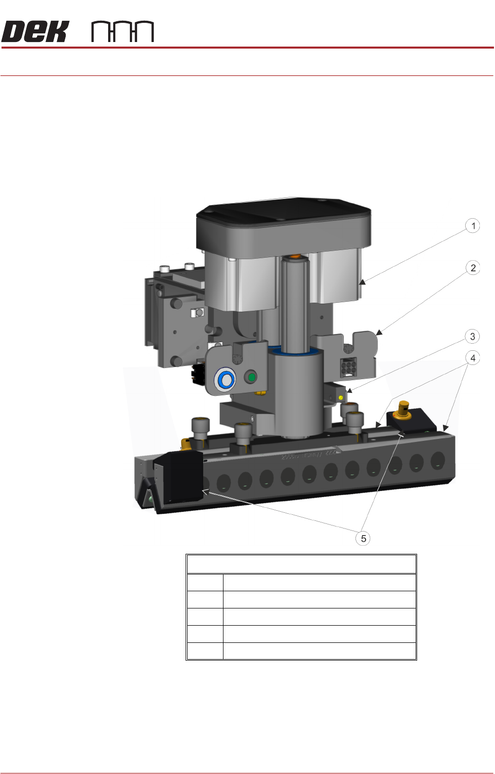
ProActiv Mechanism
1 ProActiv Mount Assembly
2 Electrical Connector Bracket
3 Proximity Sensors
4 ProActiv Squeegee Mounts
5 ProActiv Connector Mounts
PROACTIV
OVERVIEW
10.2 Technical Reference Manual Chapter Issue 5, Jan 15
Elements The ProActiv module consists of:
• A squeegee mechanism to house the sensors
• Electronic control modules and associated wiring looms
• A pair of active squeegees (sizes available: 170/200/250/300mm with or
without a pair of paste deflectors)
• A pair of proximity sensors to sense the squeegee up/down movements
Squeegee
Mechanism
The squeegee mechanism houses a pair of motors, which lift and lower the
squeegees. Driving the squeegee down, onto the stencil, creates the print
pressure needed to force the paste through the stencil apertures. The mecha-
nism has an electrical connector bracket that houses the electrical connectors,
switches and indicators, which are used to supply power and signals to the
active squeegees.
Active Squeegees The front and rear squeegees have active elements, which provide the motive
forces that are used to ‘work’ the paste.
NOTE
1. Only use the original matched ProActiv squeegee pair, as supplied with the
printer or as part of a machine upgrade. Optimum performance may not be
achieved if an alternative ProActiv squeegee pair is used. Contact ASM
customer support for assistance.
2. Handling active squeegees. Do not mishandle or drop active squeegees.
This may cause damage to the active elements. Always stow away securely.
3. Immersion of any part of the ProActiv unit in liquids causes irreparable
damage to the unit. It may also cause permanent damage when fitted to the
printer.
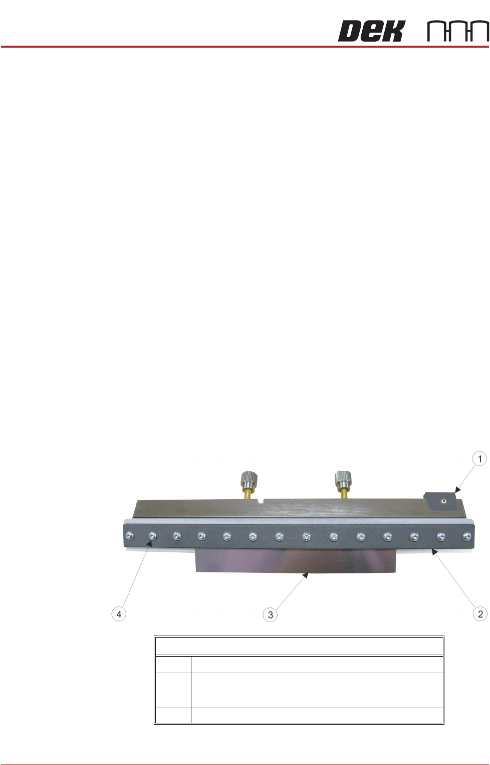
Rear View of an Active Squeegee Assembly
1 ProActiv Connector Mount
2 Mounting Bar
3 Squeegee Blade
4 Squeegee Blade Fixing Screws (14 off)
PROACTIV
OVERVIEW
Chapter Issue 5, Jan 15 Technical Reference Manual 10.3
The squeegee blades are mounted and secured to the mechanism by the
mounting bar using the fixing screws.
Each squeegee has an integral ProActiv connector mount that allows the output
from the control module to activate the squeegee.
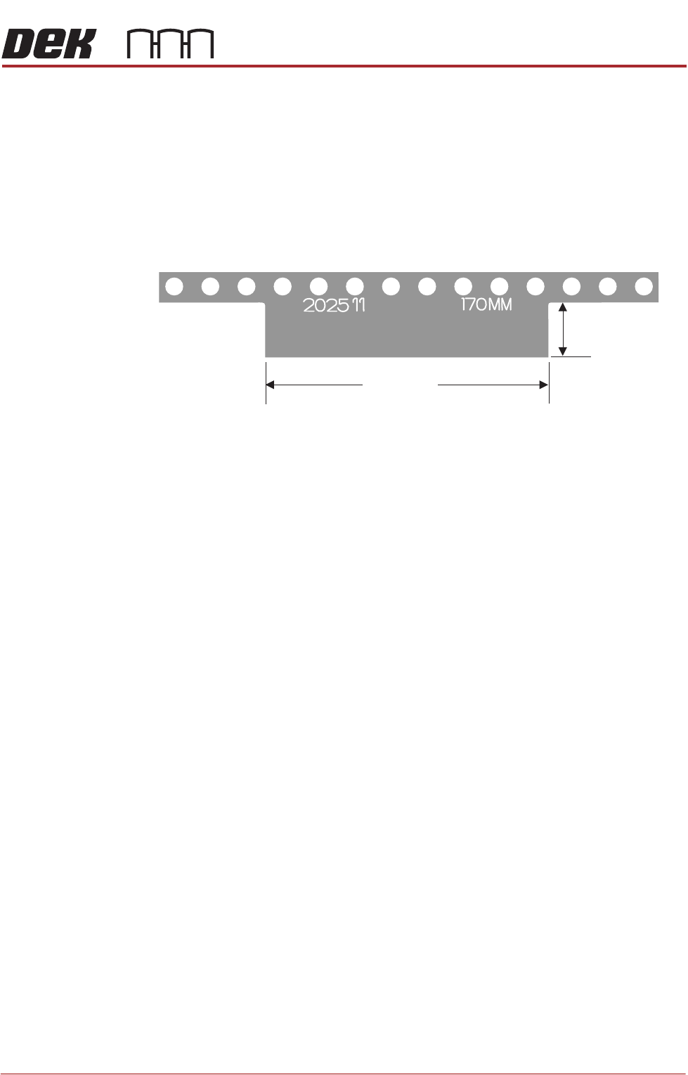
Squeegee Blades Squeegee blades are available in sizes: 170, 200, 250 and 300mm blade widths
and two blade depths, either 6 or 15mm. These measurements refer to the
portion of the blade that is used to work the paste, as shown below. The part
number and width are engraved on each blade.
Mount the blades in the active squeegee assemblies with the part number and
size facing the front.
Blade Width
6 or 15 mm Options