Micron Technical Reference V9 Volume 1.pdf - 第258页
PROACTIV MECHANICAL DETAIL 10.8 Technical Reference Manual Chapter Issue 5, Jan 15 MECHANICAL DET AIL NOTE Handling active squeegees. Do not mis hand le or drop active squeegees. This may cause damage to the active eleme…
PROACTIV
ELECTRICAL DETAIL
Chapter Issue 5, Jan 15 Technical Reference Manual 10.7
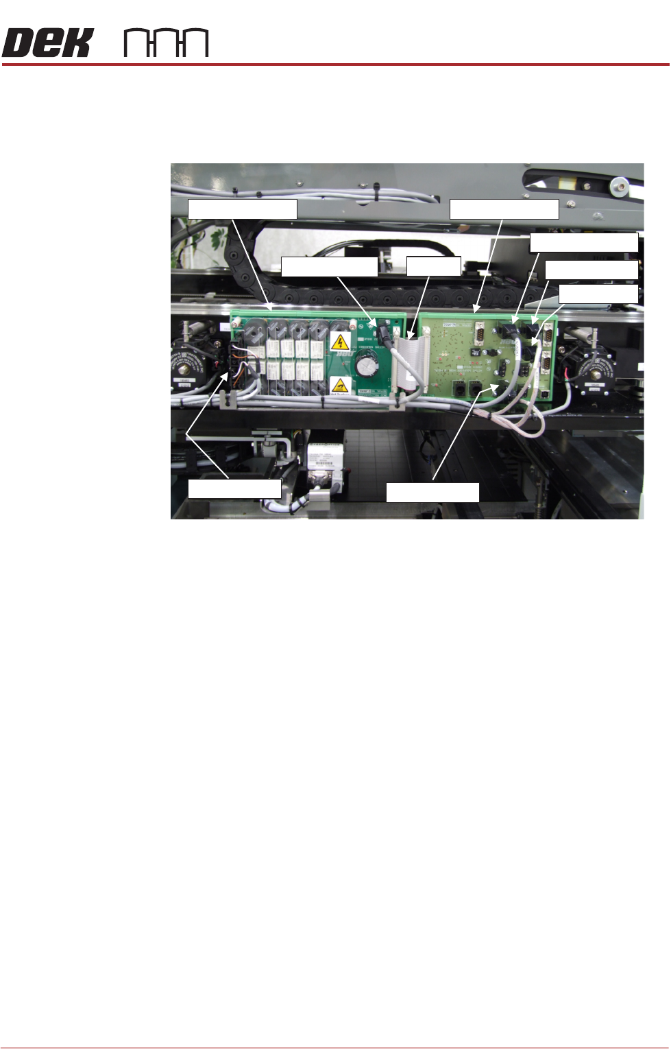
Drive Board The drive board and the node board are located together, behind the print
carriage bearing support, on the left-hand-side of the printer. The drive board
generates the signals required to drive the active elements of the squeegees.
Figure 10-1 Electronic Control Boards Located on the Printer L.H.S.
Power comes from the M37 power supply enclosure, it supplies the following
voltages: 42V, +24V SW, +24V US and +12V.
Drive signals activate a squeegee via N18PL14. This cable divides to provide
independent drive signals to the front and rear squeegees.
NOTE
I/O Connections are shown in the Machine Control Chapter.
Node Board The node board routes signals from the drive board, or the sensors and
switches, as follows:
Signals routed from the drive board to the node board across JP1:
• Enable and status indicators
Feedback signals from the node board to the drive board across JP1:
• The system is ready to activate the squeegees (enable switch)
• A squeegee has moved from dwell to contact height or vice-versa (front
and rear proximity sensors)
NOTE
I/O Connections are shown in the Machine Control Chapter.
Drive Board
Node Board
N18PL13
N18PL14
JP1
N18SK01
N18PL05
N18PL04
N18PL08
PROACTIV
MECHANICAL DETAIL
10.8 Technical Reference Manual Chapter Issue 5, Jan 15
MECHANICAL DETAIL
NOTE
Handling active squeegees. Do not mishandle or drop active squeegees. This
may cause damage to the active elements. Always stow away securely. Do not
clean too vigorously or by fully immersing in a liquid.
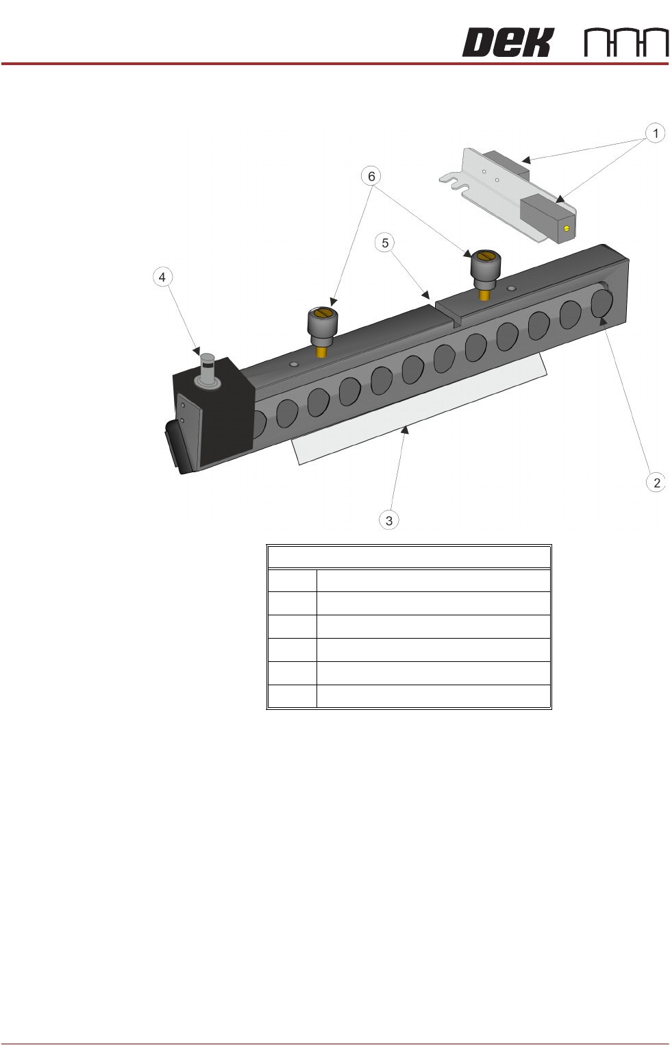
The active squeegees are fitted to the squeegee mechanism using the top
mounted locking thumbscrews. To prevent the squeegees from being fitted to
the wrong holder each squeegee is constructed with a keyway and a pair of
locking thumbscrews. The thumbscrews on the rear squeegee have their hole-
centres further apart than the hole-centres on the front squeegee. The keyway
aligns with the dowel pins on the squeegee holder.
The electrical cables connect each squeegee to the drive board via connectors
on the mount assembly bracket (9SK74/75). The cables carry power and
signals to drive the active elements in each squeegee. The cables are loomed
through the drag chain back to the drive board to plug (N18PL14).
Proximity switches located above each squeegee are used to sense when the
squeegee moves from dwell height to contact height. This movement causes
Front Active Squeegee
1 Front and Rear Proximity Sensors
2 Active Elements
3 Squeegee Blade
4 Electrical Connector Assembly
5 Locking Thumbscrews
6Keyway

PROACTIV
MECHANICAL DETAIL
Chapter Issue 5, Jan 15 Technical Reference Manual 10.9
proximity switches to trigger, if ProActiv is on, the active drive to the squeegee
blades turns ON. The active squeegee remains on until it is: turned off by the
operator, or the machine is powered down, or emergency stopped, or the
squeegee returns to either the dwell position or the home position.