Micron Technical Reference V9 Volume 1.pdf - 第264页
PROACTIV ADJUSTMENTS AND SETTINGS 10.14 Technical Reference Manual Chapter Issue 5, Jan 15 holes on the front foot assembly . 18. Fit the squeegee pressure plate to the rising table ensuring that the locating dowels inse…
PROACTIV
ADJUSTMENTS AND SETTINGS
Chapter Issue 5, Jan 15 Technical Reference Manual 10.13
the following graphic:
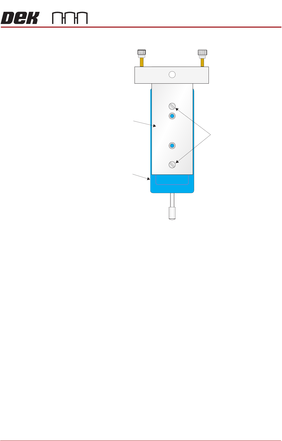
17. Fit the calibration jig to the front squeegee position using the outer mounting
Mounting Plate
Mounting Holes
Calibration Jig
A
A
S
S
PROACTIV
ADJUSTMENTS AND SETTINGS
10.14 Technical Reference Manual Chapter Issue 5, Jan 15
holes on the front foot assembly.
18. Fit the squeegee pressure plate to the rising table ensuring that the locating
dowels insert into the holes of the rising table.
NOTE
During the squeegee pressure calibration the dwell height of the rear
squeegee is 15mm regardless of the set up value. This height is set during
calibration only.
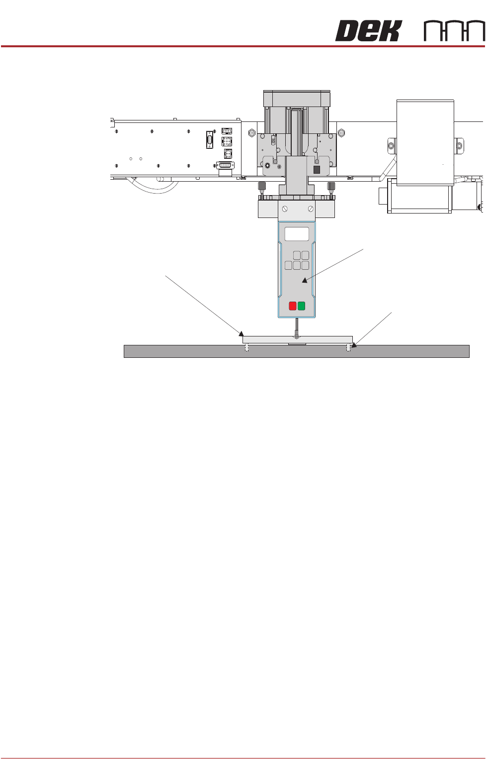
19. Switch the force meter ON and check the reading is 0kg, (ensure the force
meter is not in contact with the squeegee pressure plate).
20. Select Continue.
View on Frontof Rising Table and Squeegee M echanism
Squeegee Pressure Plate
Locating Dowel
(in 2 positions)
O
OFF
I
ON
UNITS
Zero
MAX TXD
RESET
00.00
Portable Force Gauge
(Calibration Jig)

PROACTIV
ADJUSTMENTS AND SETTINGS
Chapter Issue 5, Jan 15 Technical Reference Manual 10.15
21. The front squeegee mechanism steps down until a change in pressure is
detected and continues stepping down until the pressure value stored on the
machine is reached. If the calibration jig displays 10kg, go to Step 24.
22. Select Jog Rig.
23. Use the left and right jog buttons to move the front squeegee mechanism up
or down until the calibration jig displays 10kg.
NOTE
Achieving exactly 10kg may not be possible as some calibration jigs display
down to three decimal places.
24. Select Set Calib..
25. Select Exit.
26. The front squeegee mechanism moves to the home position. The message
‘Confirm that the pressure calibration jig has been removed.’ is dis-
played.
27. Remove the calibration jig and the squeegee pressure plate from the
machine. On completion select Yes, the table resets, the print carriage
moves to home position, board clamps open and the rear rail moves to the
board width setting.
Active Squeegee
Reference Height
This procedure sets the squeegee reference height to establish the correct print
pressure.
1. If a Ptest.dat file is not required, go to Step 7.
2. Select Maintenance.
3. Select Test Cycles.
4. Select Data Logging On.
5. Select Back.
6. Select Back.
7. Select Setup Product.
8. Select Squeegees.
9. Select Unload Screen.
10. Open the front printhead cover.
11. Remove the stencil from the printer.
12. Close the front printhead cover.
13. Press the System button.
14. Select Calibrate Heights.
15. The message ‘Ensure that the correct squeegees are fitted!’ is dis-
played.
16. Select Restore Defaults.